I have long played with the thought of having a front-panel switch on vintage oscillators so that you could apply a TEMPCO stabilizing resistor for those very rare anomalies when you want less "analog" behavior for whatever reason. The vintage Buchla 258 dual oscillator series used carbon film resistors instead of the more accurate TEMPCO later found in the to me less-interesting Buchla oscillators. (Note that all Buchla analog oscillators used polycarbonate timing capacitors, which are similar to polystyrene, both of which are more stable than mylar or other film capacitor types. The Buchlas don't drift a whole lot, especially when used with a modern power supply; a limited tracking range is the main hindrance to their typically being useful for "melodic" music, although you can certainly set them up for that if you wish. Later versions "improved" tracking range. All of which is missing that the atonal exponential FM is the real attraction here...)
However, the 258J, based upon Mark Verbos' mutant 258C design, recommends a TEMPCO resistor. When I was asked to build a dual 258J set to mount on a Buchla-style front panel, I suggested the "Vintage/Modern" switch as a possibility. I'd have to build it and test it first to see if any foibles got in the way of making it actually happen. An SPDT would appear to work just fine, although there is an audible dip and return to pitch when the switch is thrown in either direction.
TEMPCO mounting:
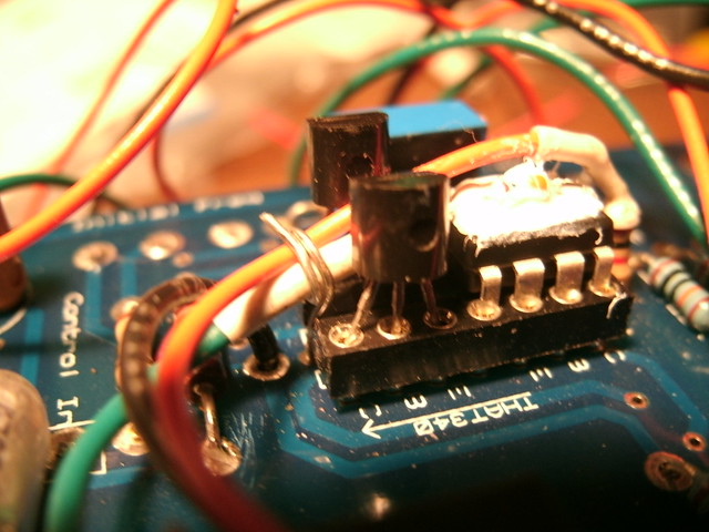
That's an SSM2220 with a pair of matched PN3565. The top of the SSM is heat-transfer greased and the TEMPCO sits across this. Note that both resistors are soldered into the pad at the SSM IC; the carbon film 2K is wired off to the switch and simply stands up off of the PCB. That's the orange wire. The TEMPCO needs to be in physical contact with the top of the SSM and the heat grease, but with its other end unsecured (not soldered into the PCB, but connected from there via wire to the switch), it simply moves around depending upon that wire's placement.
I noted a via (tiny through-hole) right in the curve of the top of the IC socket (first and last IC pins are there) and soldered in a clipped resistor lead, stood it up, and wrapped it around the heat-shrink-wrapped TEMPCO leg/wire and the carbon film resistor's wire as well, which effectively holds the TEMPCO horizontal and upon the prepared top of the SSM. Very cool, very serendipitous. The TEMPCO is the green wire and the black, the return from the DPDT switch. You can use an SPDT as well; I got DPDT in case the two resistors needed to be better isolated for any reason.
Also note that the heat-transfer grease will then get on and into everything else. :/ And that obviously, I've taken this picture before prettying up the PCB. Will remove the flux bits for delivery and likely replace this with a photo of a clean PCB.
Waveform Switch wiring:
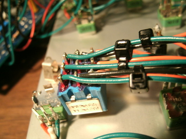
As mentioned earlier in the blog, L-1 at a few forums discovered and published that the Buchla 258 oscillator could be built with all waveform resistors present, brought out to a 3PDT switch (front panel, placed in the hole originally used by the Fine Tune pot), to allow the user to select saw or square per oscillator. The vintage factory version (258A, B, and C) had one oscillator offering saw and on the other, square. This required you to have two dual oscillators to do a detuned saw pair. Now available in a single dual oscillator if you're up to doing the wiring. (A new hole must be drilled in the front panel for a Fine Tune pot if you want one.)
10V CV Modulator Range Modification
As is also mentioned earlier in this blog, Mark Verbos pointed out in his blog that early Buchla control voltage was 15V unipolar, travelling from zero to positive 15V. Half-way through producing the 200 series, Don Buchla set a new standard of 10V, which would then sweep a modulation destination across its entire range.
People building the 258J and some other Buchla clones such as direct copies of the 292 gate will run into not only that they are optimized for use in a system where the audio level is 1.2VRMS, but also that some designs may call for 15V or 10V modulation, and not all modern or even vintage systems output that much. The 258J's Waveform CV input is one such parameter which will need to be modified for use in a 10V system, if you're stocked with more late 200 or 200e modules.
Simply replace the 680K resistor at the input with a 402K or close value.
Front Panel:
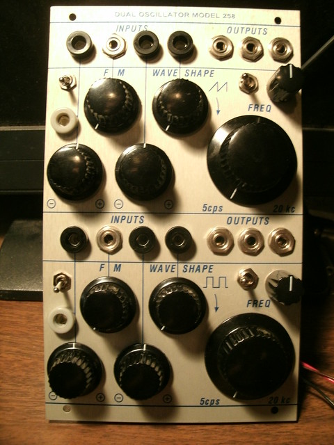
The switch directly above the large Frequency control selects between saw or square waveforms per oscillator. The switch above the gray banana (1V/Octave, calibrated via an added multi-turn trimpot) selects TEMPCO or carbon film resistors. A Fine tune control was added to the right of the Waveform switch using a Davies 1900 knob. The left of the set of three audio output jacks is from the triangle wave (buffer circuit added to the experimenter's "muck"). The second two are the sine to (alt) waveform per the original.
Note that I've used the Alpha 9mm panel-mount/PCB-mount pots here as they appear to be sealed versus the 16mm which are open (!). I've found that if you use a pliers to snap off the tiny orientation nub on the pot near the bushing, then place three washer rings on the bushing and then mount it to the panel, it will sit with just the right height to drop on the small Davies knobs with just a touch of space between them and the panel so they don't brush against it.
I may add more to this page at a later date.