Thursday, November 16, 2017

Successful laser replacement in Denon 3910

Youtube is a goldmine for tutorial videos but I found nothing on replacing the laser in the Denon 3910. I did find a video detailing replacement of a laser in a very similar model, close enough that I was able to do my 3910 and adapt to the slight differences. I've had the new laser in for a day now and it's playing both CDs and SACDs just fine. Got the NOS replacement for $17.00 from here:

https://www.ebay.com/itm/Denon-DVD3910-DVD-3910-Laser-Brand-new-Spare-Part-/122801607233?

I only took a couple of basic photos to remind where certain screw types went so sorry, no documentation...after buying a Sony 9000ES in non-working condition for $1 and throwing hours and a new laser into it and it ending up not working well enough, I simply powered ahead and replaced it on the Denon and powered it up.

DO NOT ADJUST the Allen screws which adjust the height of the assembly/beam. That may be the one thing the gent in this video did wrong. There are three videos detailing his process but this first one should give you enough information to accomplish the replacement combined with my following notes. 


Again, DO NOT ADJUST the Allen screws which adjust the height of the assembly/beam.

The 3910 has the same body as the unit in the video but a slightly different interior. The black front panel has to be unscrewed on top and bottom and pulled away a little and a metal bar across the top front held by two screws, removed to allow enough room to remove the covers on the laser assembly. 

There is a ground wire between the front panel and the laser cover which slips under the front panel where a screw holds it in place; it also is screwed down to the top of the laser assembly so make note of where it went before removing.

Definitely plug it in momentarily and extend the tray; unplug with it extended. Instead of an internal plate covering the entire top of the unit per the one in the video, there is a small black plate with four small screws on top of the laser assembly which must be removed. Then the larger cover to the laser assembly as well. The ribbon connector can probably be removed first.

The ribbon connector has a tiny bar along the top where the ribbon inserts which must be pushed out a millimeter or two before removing the ribbon and of course pushed back when the ribbon is replaced.

Two flat head screws hold a small metal panel across the far end of the laser's travel. With it removed the two bars along which the laser rides are free, but note: there are as seen in the video two springs in the small black plastic piece upon which the two metal rods sit. Using a long screwdriver lift the two bars up (near the end so you don't remove or dirty the lubricant) from beneath and gently remove the black assembly with the two springs.

The defective laser can now be removed; the right bar and the white gears are attached so slide the laser off of the left bar so it's entirely free. Remove the white gear assembly and the metal bar.


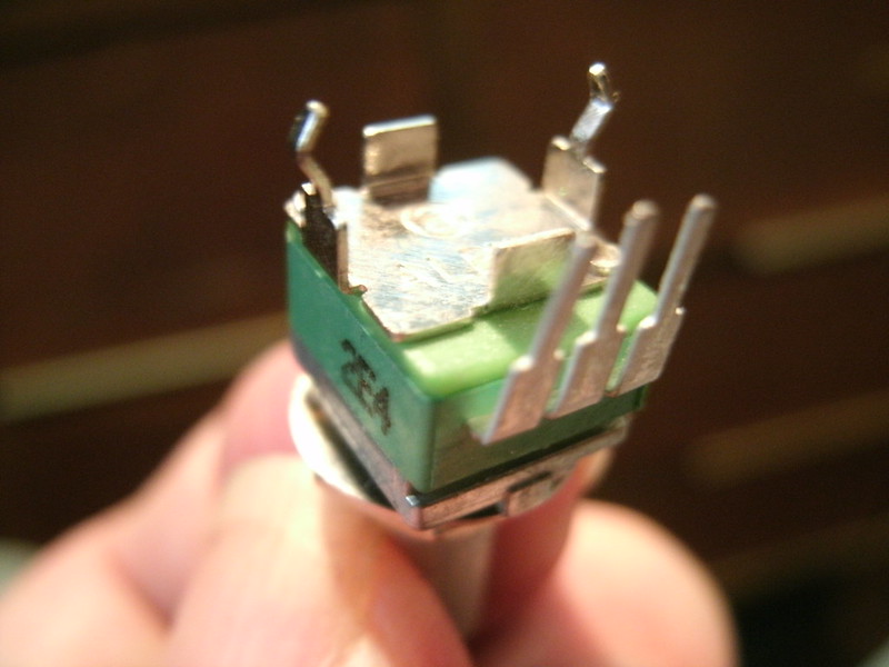
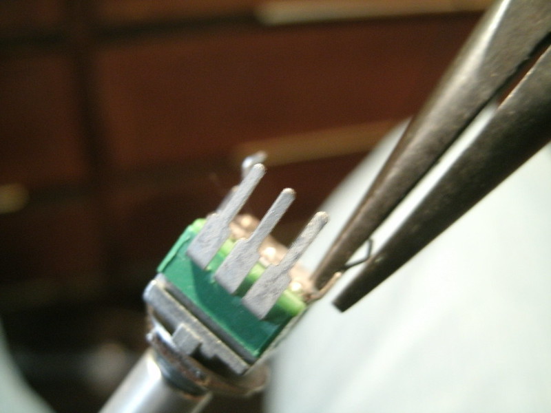
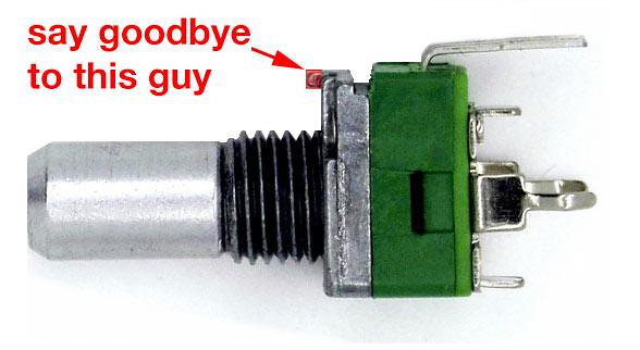
Ground yourself and unsolder the two anti-static solder blobs on the new laser mechanism (if unsure which two they are check the defective laser for reference). They're on plastic so don't melt the plastic in the process. 

The left rod along which the laser slides can be left in place; the right comes out along with the laser to remove the white gear assembly. Slide the bar into the new laser assembly and attach the white gear assembly. You can now slide this onto the left bar still in place in the unit so both bars are now fitting to the front. Again lifting them, replace the black plastic piece with the two springs and rest the bars upon them. Replace the metal top and two screws. DO NOT ADJUST the two Allen screws in that assembly at any time.

Replace the ribbon and push down the clip. Replace the two laser covers making sure to remember the two wire holders on the left side and the small ground wire to the front panel on the right. You can replace the top metal bar across the entire front and its two screws now plus the front panel with or without again plugging it in to withdraw the disc tray. Don't forget the small ground wire from the laser which is screwed down between the frame and the front panel.

Plug in power and audio and give it a whirl! I encourage anyone who enjoys this player to not worry about trying this if they've previously done a laser replacement; it wasn't very difficult and requires no self-calibration afterward. Hope you're successful and that this helped!

Monday, September 26, 2016

410 Discrete Hex AR DIY


Prototype. AR knob spacing as well as feature set may change. In this one prototype you may notice incorrect front panel text.

ORIGINAL SCHEMATIC

This is the all-transistor AR envelope from the Buchla 410 Module Cluster.

Modes include switchable Sustain or Transient (one-shot) modes, a X10 switch for very long envelope times (switching between the 1uF timing capacitor and a 10uF). Lamps indicate envelope output level. Not LEDs, so remember that lamps cannot follow the fastest times possible with this device.

Lamp circuitry is not included on this etch but may be assembled on a rectangle of perf board.


LOOPING/COMPARATOR SECTION:

The looping/comparator section is from the 212 envelope schematics and is supposed to fire an output pulse when 0.2V is reached. I didn't manage to get this section working but hopefully someone will chime in.

Initiating it would require a dual-section Mode switch, with one side wired to +15V with a diode and a small RC circuit to reduce it to a pulse, to the input.


POWER:

Ground, +15V, +24V. Small 24V power supplies can be found at surplus stores and at Mouser for not much money.


OUTPUT LEVEL:

This is a 100/410 module, which like the black-knobbed early 200 modules, outputs a +15V maximum voltage. The 110 Gates etc. require +15V to sweep their full response range. Using this with later 200 and 200e modules can pose some issues; VCAs will respond strangely. For things such as filter frequency or oscillator frequency, this is not a problem.

It should be possible to mod this circuit to output +10V; see the Modifications section at the end of this post.


CONTROL REQUIREMENTS:

Some 200e modules might not output the correct gate signal to fire these circuits. Will have to find out.


PARTS:

The prototype shown was built with 2N3904 and 2N3906 transistors instead of the indicated 2N3565 and 2N4248 and it works just fine.

Per Envelope:

5) 2N3565
3) 2N4248

for a total of

30) 2N3565 and
18) 2N4248.


Resistors:

1) 2R2 1/2W

6) 47r
6) 6M8
6) 1M
6) 220r
6) 22r
24) 47K
12) 22K
12) 3K3


Capacitors:

1) 220uF 50V electrolytic

6) 1uF Tantalum
6) 10uF Tantalum

Diodes:

12) 1N457


ETCH:

https://www.muffwiggler.com/forum/viewtopic.php?t=168870

For both the shown Quad version and for the Hex etch art as well.


CONTINUITY CHECK, PARTS LEGEND:

Hex version:

410 Hex Env 1b


410 Quad Env Parts


IN USE:


MODIFICATIONS:

The 1uF timing capacitor may be brought out to a switch selecting between it and say a 10uF for 10X slower rates. 


coffee

Friday, September 16, 2016

RIP Don Buchla.

I met Don Buchla at length when he was pitching and arranging the Buchla Lumina Marimba deal with Nearfield Electronics. We chatted for a few minutes at one point; I won't share everything he said but he mentioned playing the piano as a young man and that his family were against it, that he actually snuck out of his house to play piano on some radio show, I believe at night; it's vague now in my memory. I believe he said he used a different name on-air to get away with it. Yes, I got to see him smile. A truly brilliant man, a genius in music electronics combining his unique aesthetic for human interface and the circuitry itself. I cannot begin to describe the depth of impact his vision has upon me and always will. My heart to him and to his family. Sleep in Light.

Thursday, July 28, 2016

CP3 mixers in Buchla 106 format

DSC00458

DSC00459

Those who have known me long-term remember that I've praised the Moog Modular to the high heavens as being an amazing-sounding instrument, superior to modern designs. Among the aspects which have since been proven out, the CP3 discrete mixer saturates/distorts very pleasantly when slightly overdriven. Random oscillator fluctuations presenting a saturated bliss...even before going into that amazing filter. I was given a great deal of shit for being right.

SO. Why not add such goodness to the Buchla? Especially interesting for those using the 200e, 259, and 208 devices which would benefit from some pleasant saturation. Here we have three CP3 mixers, acting in place of the 106 discrete mixer. It behaves in the same manner, two independent three-channel mixers with their own outputs, also feeding into a final summing mixer for a single output combining ALL of the six input signals. But here, the CP3s positive and negative outputs are provided as they apparently sound different so it's up to the user to determine which for them is the most attractive in whatever patch. The "-" output is said by some to be the most attractive-sounding. Note that the individual 106 sections were inverting, so use the "-" output to mimic 106 patching such as in adding resonance to a 292 channel via feedback.

Switching is provided to determine whether the mix section A and B positive or negative outputs are sent to the summing ALL mixer section.

106 CP3 Signal Path

Here is a scientific exploration and explanation of what the circuit does to embiggen input signals with a very interesting short video.


PARTS:

The original used plenty of carbon composition resistors and every now and then 1/2W carbon film. It is possibly useful to have the 15K and 560r matched or 1% metal film. It is unknown if the carbon composition resistors used in the original circuit were matched to any extent, but since they were likely 10% tolerance types. Modern carbon composition resistors are available in 5% tolerance so you're already that much closer to any required matching.

Transistors: The 2N4058 and 2N3392 are again being manufactured and are available through Mouser.com. They retain the pinout of the vintage transistors, ECB.

You can use matched 2N3904/2N3906 but I'm not sure if it will sound the same; also, remember to make them fit the provided ECB pinout on the PCB! 3904/6 are usually EBC. One build page did indeed say the 3904/6 sound a bit edgier than the original transistors.


The heatsinks were overkill to insure functionality on that revision; you can probably get away with using two of these with nylon 4-40 type screws/nuts on the negative regulator ICs. Be sure to use a little electrical tape to protect the sinks from shorting upon any PCB traces.

The ones used in the build in the picture are here. They require electrical tape between them and the PCB to avoid any shorting. You also have to sort of slide in the power IC as you bring the clip down upon the body in order to secure the power IC. They are also through-hole designs so there are a pair of 1.5mm holes required in the PCB; drill holes are already provided. The feet must go through the electrical tape.

Also, some of the capacitors seated directly at the power ICs require solder on the top and bottom side of the PCB so first install the 7910 and then the caps and then the 7906 and caps. The potentiometer beneath this pair requires the leg which goes through the PCB to be clipped off lest it touch the heat sink.


512-LM7812CT
512-LM7910CT
863-MC7906CTG

2) 2.2uF 74-173D225X9025VWE3
3) 1.0uF 74-173D105X9025UWE3
3) .0033uF 23PS233
6) .01uF

2) 47K
3) 6K8
3) 200r
6) 100r
6) 560r
6) 15K (might want 1%)
11) 22K
3) 100r trimpots 858-64WR100LF

1) Toggle Switch 611-T201-001
6) Davies knobs 5164-1610AA
12) Tinijax 502-41
12) Tinijax nuts (one each, behind the faceplate)
1) EDAC 587-306-50-010

6) Alpha 9mm Audio A25K right-angle pots


MATCHING:

Gain needs to be matched between all transistor pairs to say within 5%. I'm not sure if all transistors of the same type need to be within a common 5% or not for equal audio levels.

GAIN STRUCTURE:

The original mixer is a 2X gain increase with an overall level control. The earliest Moog oscillators, the 901b and 901, were 1.2V output. The Buchla 100 oscillators I've cloned are supposed to be quieter than the 258s, but they aren't for some reason. The gain structure of this mixer and the differences in level mean saturation will occur at different points of the input Level controls so keep that in mind per the system in which you intend to use it. You may have to change the 22K input resistors to a different value if you're getting saturation before the 12:00 setting.

Signal sources greater than Moog and Buchla will require input resistor value changes.

Use 47K resistors for the two input section CP3s for 2X gain. Use a 22K on the top CP3, which is the summing section for both input sides, for unity gain so as to not overdrive everything too far when using 4+ inputs.

SOME PARTS ARE MOUNTED ON THE MAIN TRACE SIDE:

DSC00449

Some resistors, caps, and the potentiometers are mounted on the side with the most trace artwork. The .0033uF caps, definitely. Some of the .01uF caps can if you pay attention to using heat shrink to avoid shorts with PCB traces. The feedback resistors for each CP3 are on the trace side, as are the pots and the switch.


ETCH ARTWORK

may be downloaded HERE.


ALIGNING THE TWO SIDES FOR EXPOSURE: 

Two drill holes have been provided for alignment; the solo hole at the outer edge of where the power ICs are stuffed, and the large input pad across the PCB from there which is on both sides.

Remove the protect from one side of your two-sided PCB. Tape the trace/pot side art down. Carefully drill through these holes using a #64 or so drillbit. Fold back the transparency and brush out any particles from drilling. Expose that side. Remove the protect from the other side and align those holes over the drilled spots. Tape it down and expose.


PARTS AND CONTINUITY

 106 CP3 f4 Parts 
Continuity

106 CP3 f4 Parts

Some of the jumpers must be covered with heat shrink or similar in order to prevent shorting traces on the PCB.

Don't forget the VIA! Using a resistor leg clipping or similar, insert it through the pad and solder one side; bend it down and solder the other, then smooth down the first solder point. 


You'll have to make some modifications to each potentiometer as follows:

Alpha 9mm Potentiometer

Stock Alpha 9mm PCB-mount snap-in potentiometer, unmodified.

The two spacing tabs need to be removed. This is as simple as grasping each with a plier and rocking it back and forth until it breaks off.

The two mounting legs need to be straightened; simply pinch them with a plier:

GEDC1342

And a metal nub at the front must be removed; a dyke hand tool or a large pliers can take care of this:

Alpha 9mm

Image via THONK, who sell these with the nub already removed. Thanks!

GEDC1351

GEDC1343
Finished! This is what they'll need to be for this build. 

THONK will be stocking these with the nub already removed:

http://www.muffwiggler.com/forum/viewtopic.php?t=122962

If you're using the large heatsinks you'll need to cut the side pin on the pot which will mount beneath them so it will not contact the sinks.


PUT A BRIGHT LIGHT BEHIND THE PCB AND CHECK THE POTS FOR ANY SOLDER BRIDGES:

DSC00450
This is how all of them should look.


WIRING:


106 CP3 f4 wiring


DSC00453


CALIBRATION:

Put a VOM reading DC to the outputs and set the trimpot for each section for a minimum DC level. If it's greater than 0.5V in either polarity you might need to use 1% 15K resistors.


SUGGESTED FRONT PANEL ARTWORK:

Download HERE.


MATING THE FRONT PANEL AND PCB: 

I like to use three Alpha washers on each pot to hold them slightly back from the front panel; I've found this is the perfect spacing to allow the small Davies knobs to sit all the way upon the shaft but still slightly off of the front panel, allowing you to sit them and tighten them down without worrying about them scraping the front panel when turned, as well as providing a unified appearance. The switch requires some washers as well and the nut will sit flush with the top of the switch's shaft. Looks great!

The pots will align with the holes but the switch paddle must be moved by hand to center through its hole.


TROUBLE-SHOOTING:

-If the ALL outputs are silent, did you remember to install the VIA wire?
-If one or more CP3 circuits cannot be trimmed down to a 0.2 or less offset voltage, swap out the 15K resistors for 1% types.


Super extra thanks to guest at Muff Wiggler and Scott Stites without whom this wouldn't have happened!

Friday, March 11, 2016

Thursday, June 18, 2015

Cleaning tip for vintage stereo gear

A medium bristle toothbrush. It alone is plenty to dust along edges and around knob, switches and buttons. Use with warm, possibly slightly soapy water on tougher items:

DSC00274
Left, after cleaning; right, before.

DSC00276
Ugh.

DSC00277
Ah.

DSC00305

DSC00306

DSC00303

DSC00304
After brushing with warm, soapy water.


DSC00294

DSC00289

DSC00286
Sadly the display is plastic, not glass, and someone got packing tape across it and the glue had long since caused the plastic to bubble. Uncleanable.


After some care and cleaning...there are still scratches and bumps but it's finally clean:

DSC00308

DSC00310

Salvaging the Polk PWS110 Subwoofer

The plate amp in this model may unfortunately be faulty. Wire the driver directly to a set of the banana jack inputs and power it with an external amp. Both loud and punchy, which more of a pleasant anomaly than you'd expect.