Found one of these at a church yard sale when I lived in South Central LA. A dent at one corner shows it to have fallen from a height...didn't play discs, made mechanical noises. The net is full of stories about these developing a "no disc" or similar error.
This was four years ago. During that time I've replaced the laser mechanism thanks to very clear instructions found on the net, but it didn't work. It looked like it needed to be replaced... I've since noted comments regarding a "solder blob" often found on laser mechanisms which protect them during shipping from electrostatic damage. Today, opened it up again and watched a video on youtube on the subject, which helped me to locate the offending party on this one. It's on the far right:
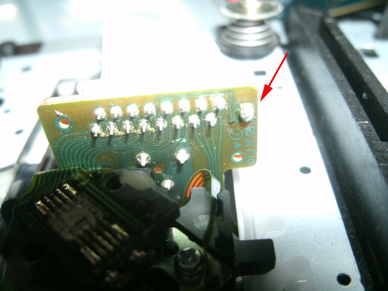
Removed it and voila, the player plays! The drawer mechanism was still shot, but it's progress! Gave it to a music-loving friend who has less than I do...and it also needed a replacement pully band for the drawer motor, as the original had become stiff. I got a few bands from mcmelectronics.com and one fit, I'm not sure of its size. I've found the items I ordered and only this part number appears to have been used:
42-1050 mcmelectronics.com
Recommending that anyone with one of these players replace
theirs as well. I don't believe it's a perfect fit but it appears to be
close enough for now.
Fixed the tray drawer issue; it wouldn't fully extend or close. Figured the motor needed replacing and it was indeed as simple as that. Got one from eBay for $5.00...it's an
RF-500TB-14415. Easily available, apparently used in more than one place for the same duty.
To replace it, follow instructions on the net regarding opening the unit (Torx screws, IIRC) and removing the entire laser/drawer (tray) mechanism. Lift the entire mechanism from the case, gently.
Note the two small connectors to the PCBs; they are
different sizes and can't be mistaken/swapped. The ribbon which connects
to the laser on the bottom is the same... Note the washers which sit beneath the rear
of the tray assembly to slightly tilt the entire thing and that the two
screws holding the tray mechanism to the case there are longer than the
two which do so at the opening in the front for the tray. Now to remove the tray...
You have to power the unit up and make sure the tray is extended (manually if necessary) before you can get to all of the screws. Make certain you do not short out anything or worse, come into contact with the deadly voltages present inside the unit at points. Do not force the tray all the way out of the assembly, it will break. When the tray is fully extended, power off the unit and disconnect the power cord.
There are two tray release mechanisms, indicated by the red arrows (the tray is of course already removed in this example:
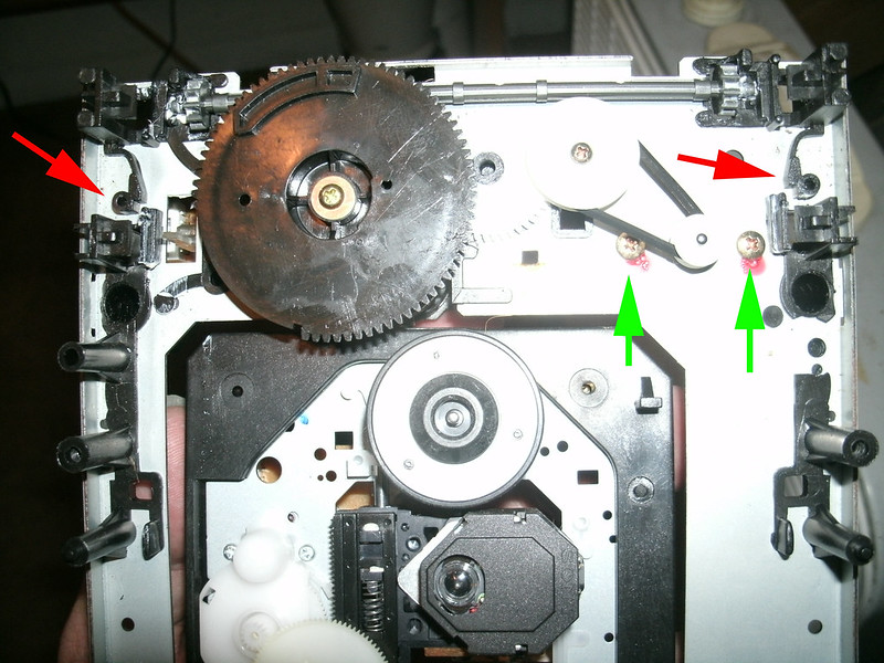
Use a pair of very small screwdrivers, inserted into the holes at the end of the arms, and pry them out away from the tray on each side, simultaneously. With these pulled outward, you may then slide the tray fully out from the assembly.
The motor is on a PCB beneath the tray, and it also houses the two microswitches. This is what you'll see when it's fully removed:
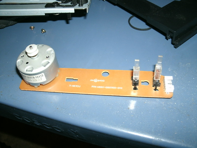
Note that the sticker with the text faces this direction when mounted correctly (it's possible to reverse mount it but that might cause damage or short it completely; not recommended to find out).
To remove the motor tray PCB first unscrew the two screws indicated by the green arrows and remove the rubber belt. Set them aside where you'll easily remember them.

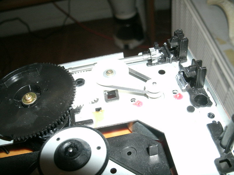
There are two plastic teeth which secure the motor tray PCB to the assembly, indicated by the green arrows. On the bottom of the PCB, pinch them together slightly and they will release:
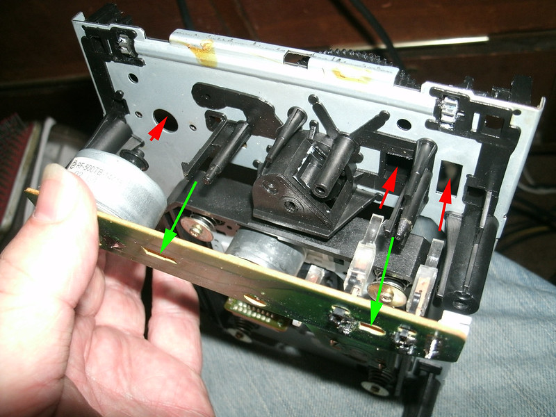
With the two motor screws and the pulley belt removed, releasing those two plastic teeth will allow you to pull the entire PCB away from the tray assembly.
Microswitch problems are another item I've read about on the net so make sure to not bend them during this entire process.
After removing the tray motor PCB, heat and remove the solder at the two points which hold the motor to that PCB:
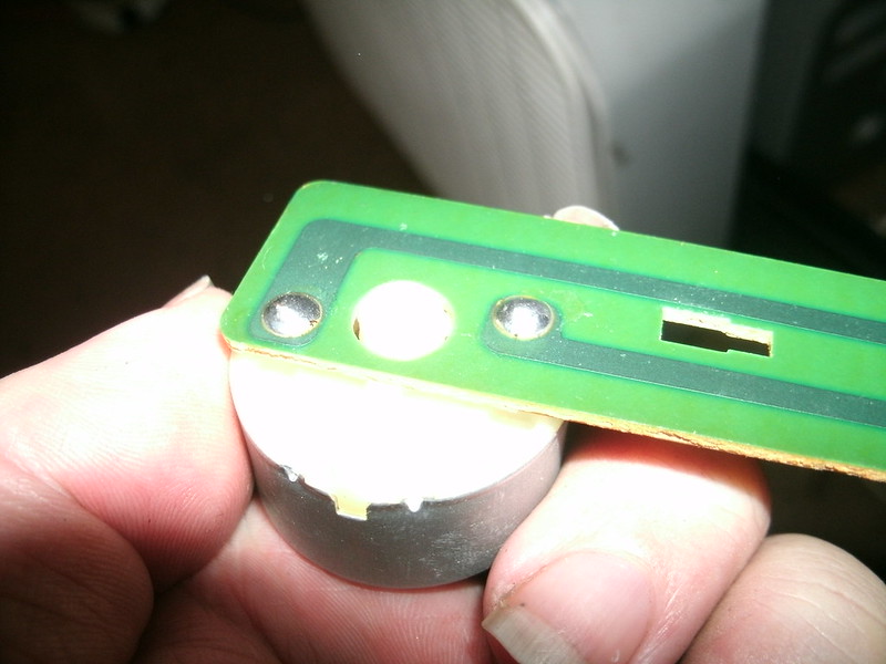
Remember the orientation for the new motor as shown in an image above. The sticker/text should be visible as shown.
If your replacement motor came with a piece of plastic for the pulley belt it might not be the correct size to go through the mounting hole in the tray assembly. Also, if it is new and unused it should have a bare shaft. Remove the white pulley disc from the old motor. If it will not release and requires more convincing, I used the bottom side of a wire clipper and gently pried it up off of the shaft, go slowly so as to not break it.
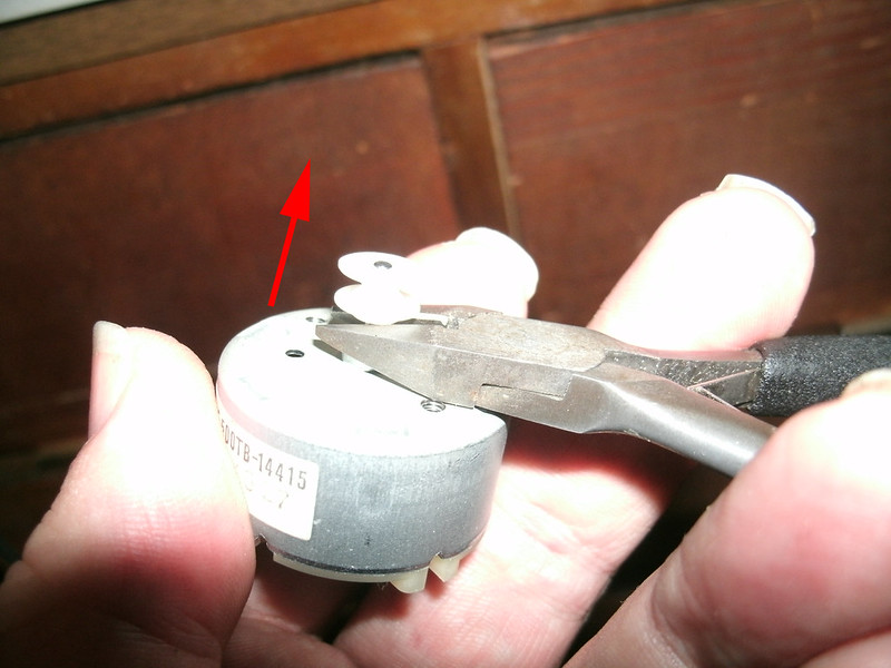 Re-mount the motor using the photo used to release the PCB. Make sure the plastic teeth come through the mounting holes on the PCB and snap into place, and that the microswitches go into and through their respective positions, taking care to not bend or displace them as you do.
Screw the motor to the tray assembly and replace the pulley belt per an above photo. You are ready to reconnect the laser ribbon and the two connectors and again, taking care not to short out anything or get into the power supply voltages, power up and test the open/close function. Should work perfectly!
When re-mounting the tray assembly be sure not to forget the two washers which go to the rear of the tray, between the legs through which the screws go and the case. You should be good to go!
If it does not work, I read an article on the net from someone who found that the circuit which drove the motor on his had gone bad, so check this link.
Further reading:
Replacing the electrolytic capacitors in the analog output section supply and the clock's capacitor
The Lampizator website also indicates that replacing all of the output electronics with Elna or similar audio grade electrolytic capacitors will definitely make a difference...how about if you hack it with the Lampizator circuit itself!


