Why not use original Vintaj Partz? It's not as bad as you'd think, and in one instance saves you a lot of money over a certain vintage part replacing an inexpensive original, and at one place, seemingly recommends against the expensive vintage part. Also find tips on adding Exponential FM, switching between saw and square waves, etc.
I'll be editing this as I learn more about the build.
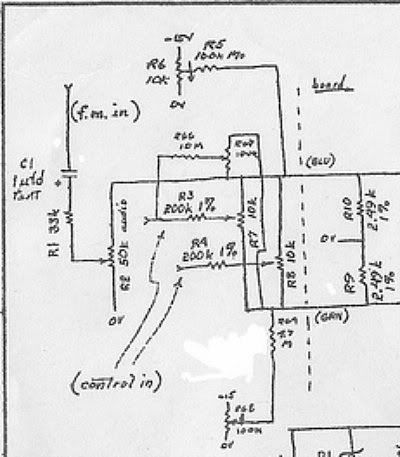
Schematic:
http://www.simple-answer.com/258mod.jpg
Diodes are Fairchild 1N457A, seven cents each at Mouser:
http://tinyurl.com/5wowafm
A matched pair is required in the sine shaper section of each oscillator so get a few when you order. (Honestly, none of Don's oscillator schematics states that these components including the associated resistors need be matched or even 1%, but what are you gonna do.)
PN3565 transistors are 21 cents each at Mouser:
http://tinyurl.com/6hzksd6
A matched pair are required. Note that the pinout is left to right EBC. They are Q7 and Q8 in this project. Not needed if you're using a THAT340.
Q9, a PNP transistor. Originals use a 2N4248. Available here for 20 cents each. I don't know about minimum orders. Second from the bottom.
http://midwestsurplus.net/contents/en-us/d30_02.html
If I remember correctly, this is only used for squaring the output of the core.
Sine shaper JFET, Q10:
The original uses a 2N4339; rare and expensive, especially since you'll have to get enough to select a correct Idss value.
The J201 and 2N4339 indeed have similar but not exact Idss ranges, which is the important bit for the sine shaper. I bought 30 J201 off eBay and got two with an idss in the .8x range, four in the .7x, and the rest were well below that, in the middle of its indicated range. Buchla specified the sine shaper as requiring an idss from between .7 to 1.2, "preferably" .8 to 1.1. I find that .8 and up is just fine for this transistor.
I've since purchased 200 J201 and found only one with a .90 Idss value, and none higher. It can max out at 1.0, but I didn't see any near that. The J202's Idss range is way too high for even a few to fall into this required range.
The 2N3819 is way higher than this, even for its minimum which in one datasheet is stated as 2.0; you may find interesting distortion waveforms from this...
Results of replacing a selected 2N4339 with a selected J201:
The J201 ends up sounding pretty much the same as the 2N4339. The 2N4339 just feels "stronger" in this circuit, however. Yes, these things matter to me.
But obviously, the J3RK-recommended J201 will provide a sine-like result (though never perfect from this particular oscillator) for cheap, compared to purchasing several 2N4339 and selecting a few usefuls!
I can post that at the far end of the purity trim, it does sound different with the J201; it becomes a rather thin square-ish wave).
Test rig for determining Idss:
http://www.forsselltech.com/media/attachments/JFET_Jig1.pdf
Or more simply:
-Alligator clip the + VOM lead (set it to DC current) to a 9V battery's + terminal
-Clip the - VOM lead to the FET's Drain pin
-Clip the FET's G and S pins together and on the other end, to the battery's - terminal.
Ignore everything in the above PDF below grounding the transistor's S. In the diagram, "ground" is the negative battery terminal. A milliamp meter, one 9V battery, three alligator clips, and you're in business. D goes to the milliamp meter; G and S go to the negative battery terminal; a single clip to both leads is fine. The Fairchild J201 I got off eBay have a pinout of DGS, so I just pried out the D pin a bit and off I went. Be careful. I managed to connect the wrong leads and burned out a 2N4339 just like that. Got VERY hot, then didn't measure Idss at all. sadface
Switch for selecting Square or Saw waveforms
You'll see some "Square/Saw" resistor seating on the board; the originals had one of the dual oscillators set up as a square wave, the other a saw. J3RK provides a choice for every oscillator you build. Kudos!
This is for a waveform that is added to the sine wave, by turning the Waveform pot and/or by connecting a positive CV to the Waveform input. The result is, on a scope or DAW, NOT a perfect waveform. This is not a problem. It doesn't sound imperfect, it sounds a bit more beefy than a "pure" saw or square. (You can tap the pure square waveform, regardless of what you stuff in the "Saw/Square" sections, from a pad on this board intended for just such an emergency. It requires a buffer but that's what the MUCK is for.)
If you wish to have a switch between the "dirty" saw and square that are controlled by the Waveform pot and added to the main output, try this, it's confirmed to work. Thanks to L-1 over at electro-music.com's DIY forum, who posted this; a very clever catch. I'd stared at the 258 schemos for years and never made that connection. L-1's post and pic are found here:
http://electro-music.com/forum/viewtopic.php?t=16502&start=125
Full instructions are found on page 6 of the Muffwiggler build thread. Please see that page for a handy wiring diagram by emdot ambient:
http://www.muffwiggler.com/forum/viewtopic.php?t=31038&postdays=0&postorder=asc&start=100
3PDT switch (be careful that you keep the saw and square "sides" separate as the switch will likely move around enough to require color-coded wiring etc. to maintain easy trouble-shooting). Mine has connections engaged per a lever fashion; when the switch paddle is down, the center and the upper connections are engaged, whereas a slide switch would show a 1:1 positional result.
As the switch itself is fairly deep, requiring a certain depth of front panel standoff, I've simply stuffed resistors standing up, or perpendicular to the PCB. Don't forget a bit of heat-shrink tubing for these connections. I just cut the resistor lead off to about 1/4" and solder the wire to it; I didn't twist the wire onto them.
Switch 1 connections, "Saw/Sqr 0 and 1".
-Left pad of the "0" has a 150K to the switch Saw side.
-Left pad of the "1" has a 330K to the switch Square side.
-Either of the two pads on the right, which are connected, at the 68K, out to the switch center.
Switch 2 connections, "Saw/Square 2 and 3".
-Left pad of the "3" has an 820K to the switch Saw side.
-Right pad of the "2" has a 680K to the switch Square side.
-The two center pads are used for the switch center.
Switch 3 connections, "Saw/Square 4".
-Two resistors are mounted in the bottom pad, a 470R to switch Saw
-and a 2K2 to the switch Square side.
-The top pad at the 680R is for the switch center.
Cheap 3PDT switch, the ones I'm using:
http://www.allelectronics.com/index.php?page=search&search_query=3pdt
Exponential FM.
Audio in to a 1uF tantalum cap (positive away from the input) to a 33K resistor to the 50K audio taper pot to the CV summing path. It may be possible to use one of the J3RK "1V/Octave" inputs for this path, obviously losing the 100K resistor specified there; I'll report my results when available.
You can add this via a swich after the 50K audio pot if you mount the tantalum cap and resistor at the front panel; switch out to the Linear FM input (jumper the cap and resistor) and also at the Exponential CV Control/Sum input. It's just another input at that point. Provides true chaotic character when two fairly high frequency oscillators FM each other. Zero capacity for keyboard tracking with recognizable pitch here, but many, many sounds are available that to my knowledge no other oscillator will produce, in terms of going from a sine out to pitched noise in a single knob change.
It is seen here at the far left of this schematic, of the earlier Buchla 258A:
http://tinyurl.com/649jqpj
I do note that when I attempt this, the results are not what I attain on an original or on my "clone". This is likely due to the fact that the old version has a CV sensitivity of 2V/Octave. It is worth considering the addition of a gain stage, especially one capable of some 10X or more, as the original version produces far more wicked expo FM when driven by such a gain stage...and this is what has been putting me off from finishing my J3RK clones, this lack of original character exponential FM, which is my most important function from this design!
Exponential FM path values.
Note that the last version of the Buchla 258 (the "B") prior to the "C" upon which this is based, used a 1.0uF Kemet tantalum capacitor and 33K resistor in line prior to the amount pot (could also of course be after). This is for the exponential FM.
I'm currently experimenting with expo FM and have so far not gotten the results I'd expect. Working on it, will post.
Linear FM variations...
There is a schematic not on the web which comes after the common "C" schemo, and there are a few changes. See also the circuit board photo below. One of interest to J3RK builders are the values in the Linear FM path: a 4.7uF Kemet tantalum capacitor (of course try WIMA poly, etc.) and a 68K resistor. J3RK's silkscreen calls for a 10K resistor; find out what you like.
Integrated Circuit Variations
741 Integrated Circuits were used in the original for CV summing and all other ICs, but here only the two output ICs are the same as the vintage version. The 741s dark character is useful when doing chaotic FM via sine waves, two oscillators exponentially FM'ing each other at pretty high frequencies. Would likely be too bright if using a TL071, but you be the judge. Not sure how much difference it would make on something like a saw wave. I obviously hope that a 741 in the CV summing will provide a modicum of inaccuracy per the original.
Here is the parts side of a vintage Buchla 258C, from which this hybrid is drawn:
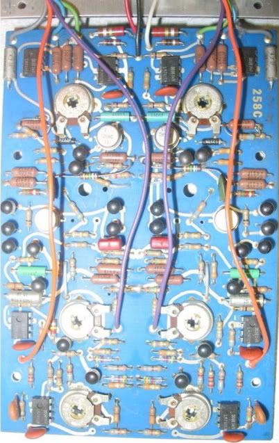
If you are anal about making your mutant 258 more like the original, here are some hints from the photo:
-Note that the 220pf is the light brown ceramic at the bottom outside. Types other than ceramic might not produce any sort of audible difference.
-The 10R 1/4W and 2.2R 1/2 at the power supply inputs are Allen Bradley carbon comp. Mouser now has a carbon comp resistor supplier:
http://tinyurl.com/3p76lk4
-Note that the 258B actually specified carbon comp resistors at certain other places in the circuit, including the 2.2K and 470Rs used in the square/saw selection, respectively. All 2.2, 4.7, and 1.0 multipliers were supposed to be carbon composition resistors, 1/4W, 10%. Says so right on the schematic. This of course includes the 2K2, 470R, and on the 258B, 4.7M, 10K, 1K (selected for 1%), etc.
-The original used a single 15uF Kemet tantalum capacitor to bypass the positive supply rail; none were used to bypass the negative rail so far as I know. It is visible as the horizontal silver piece just above the second IC from the bottom, sitting at the outer edges of the board.
I have used 15uf electrolytic for positive supply bypass in my mutant build and stuffed nothing into the negative bypass cap setting, as the original only had 15uF positive rail bypass.
-75% of the ICs were provided ceramic bypass caps (.01 on the 258A). I don't worry that there are none on the mutant version.
-The large resistors on the original are 1% type, with the rest being 5% or so, and a few carbon comp as well. Where 1% is not specified, I'm using 5% unless I only have 1% "in stock". I note that the Bucha 258B actually specified certain resistors be carbon comp. I'm not bringing that into my own mutant 258 build, however.
-The large vertical silver pieces at the top outer edges are the tantalum Linear FM caps. Note that your mutant build boards specify a 15uF electrolytic caps. No problem, go with what sounds best to you, but note that a 4.7uF value is depicted. The board picture is of a later version using different values.
Be sure to thank J3RK for the great project! And a silent thanks to Don Buchla and Mark Verbos!
I'll be editing this as I learn more about the build.
Schematic:
http://www.simple-answer.com/258mod.jpg
Diodes are Fairchild 1N457A, seven cents each at Mouser:
http://tinyurl.com/5wowafm
A matched pair is required in the sine shaper section of each oscillator so get a few when you order. (Honestly, none of Don's oscillator schematics states that these components including the associated resistors need be matched or even 1%, but what are you gonna do.)
PN3565 transistors are 21 cents each at Mouser:
http://tinyurl.com/6hzksd6
A matched pair are required. Note that the pinout is left to right EBC. They are Q7 and Q8 in this project. Not needed if you're using a THAT340.
Q9, a PNP transistor. Originals use a 2N4248. Available here for 20 cents each. I don't know about minimum orders. Second from the bottom.
http://midwestsurplus.net/contents/en-us/d30_02.html
If I remember correctly, this is only used for squaring the output of the core.
Sine shaper JFET, Q10:
The original uses a 2N4339; rare and expensive, especially since you'll have to get enough to select a correct Idss value.
The J201 and 2N4339 indeed have similar but not exact Idss ranges, which is the important bit for the sine shaper. I bought 30 J201 off eBay and got two with an idss in the .8x range, four in the .7x, and the rest were well below that, in the middle of its indicated range. Buchla specified the sine shaper as requiring an idss from between .7 to 1.2, "preferably" .8 to 1.1. I find that .8 and up is just fine for this transistor.
I've since purchased 200 J201 and found only one with a .90 Idss value, and none higher. It can max out at 1.0, but I didn't see any near that. The J202's Idss range is way too high for even a few to fall into this required range.
The 2N3819 is way higher than this, even for its minimum which in one datasheet is stated as 2.0; you may find interesting distortion waveforms from this...
Results of replacing a selected 2N4339 with a selected J201:
The J201 ends up sounding pretty much the same as the 2N4339. The 2N4339 just feels "stronger" in this circuit, however. Yes, these things matter to me.
But obviously, the J3RK-recommended J201 will provide a sine-like result (though never perfect from this particular oscillator) for cheap, compared to purchasing several 2N4339 and selecting a few usefuls!
I can post that at the far end of the purity trim, it does sound different with the J201; it becomes a rather thin square-ish wave).
Test rig for determining Idss:
http://www.forsselltech.com/media/attachments/JFET_Jig1.pdf
Or more simply:
-Alligator clip the + VOM lead (set it to DC current) to a 9V battery's + terminal
-Clip the - VOM lead to the FET's Drain pin
-Clip the FET's G and S pins together and on the other end, to the battery's - terminal.
Ignore everything in the above PDF below grounding the transistor's S. In the diagram, "ground" is the negative battery terminal. A milliamp meter, one 9V battery, three alligator clips, and you're in business. D goes to the milliamp meter; G and S go to the negative battery terminal; a single clip to both leads is fine. The Fairchild J201 I got off eBay have a pinout of DGS, so I just pried out the D pin a bit and off I went. Be careful. I managed to connect the wrong leads and burned out a 2N4339 just like that. Got VERY hot, then didn't measure Idss at all. sadface
Switch for selecting Square or Saw waveforms
You'll see some "Square/Saw" resistor seating on the board; the originals had one of the dual oscillators set up as a square wave, the other a saw. J3RK provides a choice for every oscillator you build. Kudos!
This is for a waveform that is added to the sine wave, by turning the Waveform pot and/or by connecting a positive CV to the Waveform input. The result is, on a scope or DAW, NOT a perfect waveform. This is not a problem. It doesn't sound imperfect, it sounds a bit more beefy than a "pure" saw or square. (You can tap the pure square waveform, regardless of what you stuff in the "Saw/Square" sections, from a pad on this board intended for just such an emergency. It requires a buffer but that's what the MUCK is for.)
If you wish to have a switch between the "dirty" saw and square that are controlled by the Waveform pot and added to the main output, try this, it's confirmed to work. Thanks to L-1 over at electro-music.com's DIY forum, who posted this; a very clever catch. I'd stared at the 258 schemos for years and never made that connection. L-1's post and pic are found here:
http://electro-music.com/forum/viewtopic.php?t=16502&start=125
Full instructions are found on page 6 of the Muffwiggler build thread. Please see that page for a handy wiring diagram by emdot ambient:
http://www.muffwiggler.com/forum/viewtopic.php?t=31038&postdays=0&postorder=asc&start=100
3PDT switch (be careful that you keep the saw and square "sides" separate as the switch will likely move around enough to require color-coded wiring etc. to maintain easy trouble-shooting). Mine has connections engaged per a lever fashion; when the switch paddle is down, the center and the upper connections are engaged, whereas a slide switch would show a 1:1 positional result.
As the switch itself is fairly deep, requiring a certain depth of front panel standoff, I've simply stuffed resistors standing up, or perpendicular to the PCB. Don't forget a bit of heat-shrink tubing for these connections. I just cut the resistor lead off to about 1/4" and solder the wire to it; I didn't twist the wire onto them.
Switch 1 connections, "Saw/Sqr 0 and 1".
-Left pad of the "0" has a 150K to the switch Saw side.
-Left pad of the "1" has a 330K to the switch Square side.
-Either of the two pads on the right, which are connected, at the 68K, out to the switch center.
Switch 2 connections, "Saw/Square 2 and 3".
-Left pad of the "3" has an 820K to the switch Saw side.
-Right pad of the "2" has a 680K to the switch Square side.
-The two center pads are used for the switch center.
Switch 3 connections, "Saw/Square 4".
-Two resistors are mounted in the bottom pad, a 470R to switch Saw
-and a 2K2 to the switch Square side.
-The top pad at the 680R is for the switch center.
Cheap 3PDT switch, the ones I'm using:
http://www.allelectronics.com/index.php?page=search&search_query=3pdt
Exponential FM.

Audio in to a 1uF tantalum cap (positive away from the input) to a 33K resistor to the 50K audio taper pot to the CV summing path. It may be possible to use one of the J3RK "1V/Octave" inputs for this path, obviously losing the 100K resistor specified there; I'll report my results when available.
You can add this via a swich after the 50K audio pot if you mount the tantalum cap and resistor at the front panel; switch out to the Linear FM input (jumper the cap and resistor) and also at the Exponential CV Control/Sum input. It's just another input at that point. Provides true chaotic character when two fairly high frequency oscillators FM each other. Zero capacity for keyboard tracking with recognizable pitch here, but many, many sounds are available that to my knowledge no other oscillator will produce, in terms of going from a sine out to pitched noise in a single knob change.
It is seen here at the far left of this schematic, of the earlier Buchla 258A:
http://tinyurl.com/649jqpj
I do note that when I attempt this, the results are not what I attain on an original or on my "clone". This is likely due to the fact that the old version has a CV sensitivity of 2V/Octave. It is worth considering the addition of a gain stage, especially one capable of some 10X or more, as the original version produces far more wicked expo FM when driven by such a gain stage...and this is what has been putting me off from finishing my J3RK clones, this lack of original character exponential FM, which is my most important function from this design!
Exponential FM path values.
Note that the last version of the Buchla 258 (the "B") prior to the "C" upon which this is based, used a 1.0uF Kemet tantalum capacitor and 33K resistor in line prior to the amount pot (could also of course be after). This is for the exponential FM.
I'm currently experimenting with expo FM and have so far not gotten the results I'd expect. Working on it, will post.
Linear FM variations...
There is a schematic not on the web which comes after the common "C" schemo, and there are a few changes. See also the circuit board photo below. One of interest to J3RK builders are the values in the Linear FM path: a 4.7uF Kemet tantalum capacitor (of course try WIMA poly, etc.) and a 68K resistor. J3RK's silkscreen calls for a 10K resistor; find out what you like.
Integrated Circuit Variations
741 Integrated Circuits were used in the original for CV summing and all other ICs, but here only the two output ICs are the same as the vintage version. The 741s dark character is useful when doing chaotic FM via sine waves, two oscillators exponentially FM'ing each other at pretty high frequencies. Would likely be too bright if using a TL071, but you be the judge. Not sure how much difference it would make on something like a saw wave. I obviously hope that a 741 in the CV summing will provide a modicum of inaccuracy per the original.
Here is the parts side of a vintage Buchla 258C, from which this hybrid is drawn:

If you are anal about making your mutant 258 more like the original, here are some hints from the photo:
-Note that the 220pf is the light brown ceramic at the bottom outside. Types other than ceramic might not produce any sort of audible difference.
-The 10R 1/4W and 2.2R 1/2 at the power supply inputs are Allen Bradley carbon comp. Mouser now has a carbon comp resistor supplier:
http://tinyurl.com/3p76lk4
-Note that the 258B actually specified carbon comp resistors at certain other places in the circuit, including the 2.2K and 470Rs used in the square/saw selection, respectively. All 2.2, 4.7, and 1.0 multipliers were supposed to be carbon composition resistors, 1/4W, 10%. Says so right on the schematic. This of course includes the 2K2, 470R, and on the 258B, 4.7M, 10K, 1K (selected for 1%), etc.
-The original used a single 15uF Kemet tantalum capacitor to bypass the positive supply rail; none were used to bypass the negative rail so far as I know. It is visible as the horizontal silver piece just above the second IC from the bottom, sitting at the outer edges of the board.
I have used 15uf electrolytic for positive supply bypass in my mutant build and stuffed nothing into the negative bypass cap setting, as the original only had 15uF positive rail bypass.
-75% of the ICs were provided ceramic bypass caps (.01 on the 258A). I don't worry that there are none on the mutant version.
-The large resistors on the original are 1% type, with the rest being 5% or so, and a few carbon comp as well. Where 1% is not specified, I'm using 5% unless I only have 1% "in stock". I note that the Bucha 258B actually specified certain resistors be carbon comp. I'm not bringing that into my own mutant 258 build, however.
-The large vertical silver pieces at the top outer edges are the tantalum Linear FM caps. Note that your mutant build boards specify a 15uF electrolytic caps. No problem, go with what sounds best to you, but note that a 4.7uF value is depicted. The board picture is of a later version using different values.
Be sure to thank J3RK for the great project! And a silent thanks to Don Buchla and Mark Verbos!