The Buchla 144 dual square wave generator can be heard on Subotnick's "Silver Apples of the Moon". It features audio-rate FM as well as an audio-rate Amplitude Modulation path.
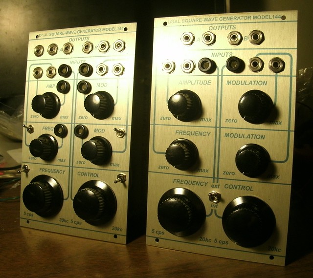
Right: Standard 144. Left: Extended module featuring sawtooth waveform outputs, switched extreme FM, switched silver mica (factory) and styrene timing caps, and a 110 Quad Gate board for voltage control of all AM and FM signal path indexes. That didn't work out due to the 110 having a slight bleed which is fine for audio duties (really low) but when audio-rate FM is concerned, no go.
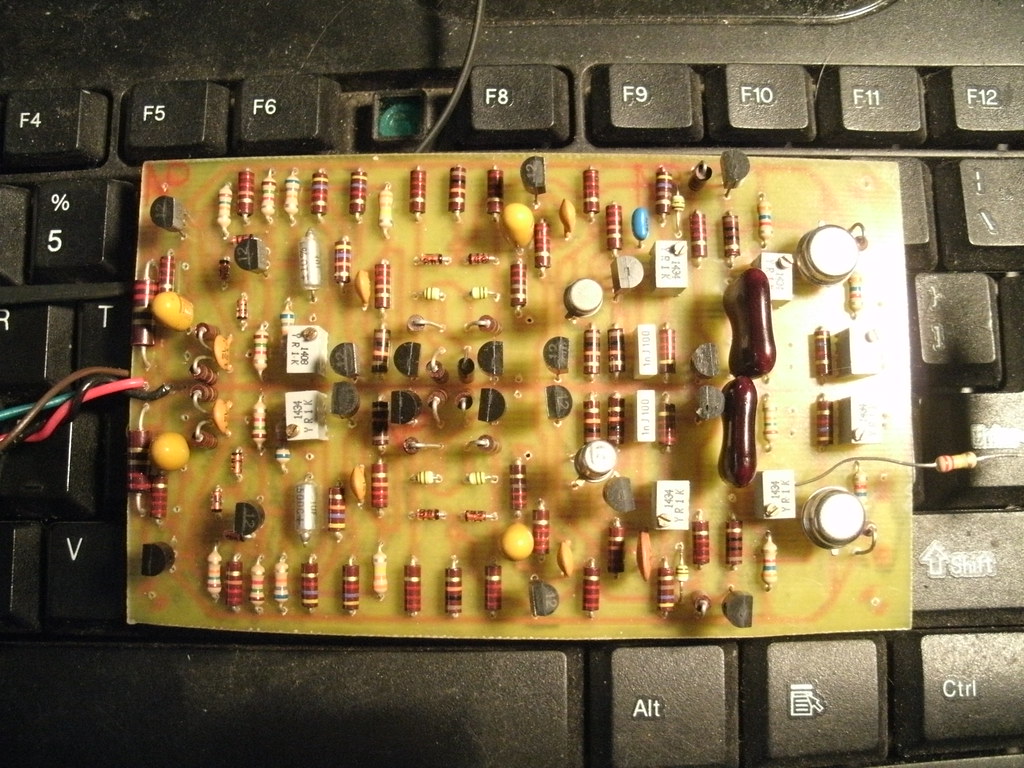
Build of the provided etch artwork. Note the two large 1/2W 2R2 resistors at the power input.
EXPECTATIONS:
This is a great-sounding oscillator and the sawtooth wave addition is quite nice. However, I'm not yet certain that there is any tracking possible with it other than an arbitrary scale, so do not expect the two oscillators to follow each other very well at all, and know that to have them track in unison tuning melodically, you'll need to use CV controllers which provide separate control and output rows, one per oscillator, to tune every set of notes.
POWER:
Ground and +15V.
PARTS:
The matched, dual transistor IT122 or ITE122 or LS122 is used here as is also used in the 110 Gates and 111. A matched pair of 2N3904 (?) may suffice as replacement. The 122 is much more closely matched than the MD708B which is used in the 158 Dual Sine-Saw Generator.
2N3391A, also used in early Moog Modules, is currently $0.58 at Mouser.com. 610-2N3391A. The trace layout accommodates its ECB pinout. Fairchild's version (obsoleted) shared the same pinout.
2N3565 may possibly be substituted with 2N3904. There is one matched pair per oscillator, for gain (Hfe).
2N4916, 2 per oscillator. 2N3906 may possibly function here. Untested.
2N5020 at mouser.com, 2 per build, to replace U147. Mouser part 106-2N5020
The timing capacitor was originally a huge Mallory polyester type. It looks to be the .0022uF near the second 2N4916. I've provided solder pads for a few variations depending upon taste, including 5mm for box-type caps, 14mm for polystyrene (or polycarbonate as is used in all other Buchla timing cores), or perhaps even very large .0022uF Silver Mica.
There are tantalum capacitors used in the signal path on the original. Elna Silmic II "audio" type capacitors, as well as Nichicon "Super Through" (which may not be available in small ratings) and Panasonic FC electrolytics may be substituted for a potentially different sonic character. The two 15uF tantalum per oscillator (4 total) are provided for in SMD form and live on the bottom / solder side of the PCB.
Five FD111 silicon diodes are listed but I've been unable to source any. The 1N4148 is listed as a potential substibute, as well as BAW62, BAW76, and BAX95. 75V, faster than 5ns.
Eight 1K 6mm multiturn trimpots, although standard 3/8" trimpots are possible here. Inline footprint.
Carbon Composition resistors, 1/4W. There is contention regarding their use in such circuits with though running along the potentially true and logical conclusion that Don used these because of availability and perhaps pricing compared to other types. Some people say these are slightly noisier than carbon film and metal film and that their "magic" only occurs when they are driven at very high voltages, producing a 2nd Harmonic distortion. Others will seek non-magnetic tantalum resistors such as Audio Note and Takman brands or Vishay 1% non-magnetic types. Some will stuff this unhesitatingly with 1% metal film. For those interested in coming as close to the original, Mouser and other component houses carry Kamaya and other brands of modern CC 1/4W types, 5%. Note that for those resistors which were 10% in the original, this is an immediate doubling of accuracy. Vintage AB resistors rise in value with age so they may now be outside of the generous 10% definition.
It would seem to me that a system 100, stuffed with all 1% resistors, would be pretty damn boring in terms of actual use / interaction.
BOM:
Transistors:
2) IT122 or ITE122 or LS122 from Linear Systems, or perhaps matched 2N3904 or similar.
4) 2N4916
12) 2N3565 or perhaps 2N3904, matched pair per generator for Vbe
2) 2N3391A, Mouser 610-2N3391A
2) 2N5020 in place of the U147. Mouser part 106-2N5020
2N3565 and 2N4916 are available at unicornelectronics.com.
Capacitors:
2) 47pF ceramic disc
2) 100pf ceramic disc
6) 910pF ceramic disc or film. .001 may substitute.
2) .001 ceramic disc or film.
2) .0022uF polyester or any film or silver mica*
2) 1uF tatalum
4) 15uF tantalum SMD, Mouser 74-TR3D156K035C0150
2) 56uF tantalum, Mouser 80-T322E566K015AT, $4.00 each. Or, 56uF Elna Silmic II or equivalent electrolytic type.
*The original were large Mallory PVC 600V polyester film caps. The modern equivalent are "Orange Drop" types, available at Mouser or Small Bear.
10) FD111 diodes, substitute indicated as 1N4148. Perhaps match the pair per generator at the matched 2N3565.
Resistors:
5% 1/4W carbon composition (Kamaya, etc.) unless noted:
2) 470r
10) 4K7
6) 47K
2) 220r
12) 2K2
6) 22K
2) 220K
2) 1K
18) 10K
2) 1K5
4) 15K
2) 2R2 1/2W
Use of 5% carbon film resistors is fine.
Carbon Film 5%, 1/4W:
2) 900r
4) 3K6
2) 330K
Trimmers:
8) 1K 6mm or 3/8"
Potentiometers:
2) 10K linear for Frequency Control
4) 50K audio for Frequency Modulation and Amplitude Modulation
Hardware:
8) Tinyjax
2) Black banana jacks
Switch for Internal / External CV Control:
1) Panel-mount DPDT, Mountain or CK
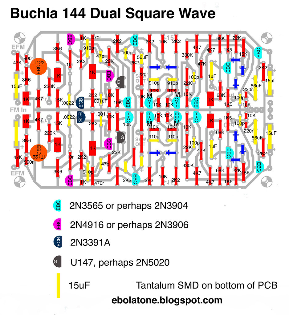
ORIGINAL SCHEMATIC:
http://electro-music.com/forum/phpbb-files/buchla_1440_1_200_137.jpg
My build does not include one trace, the one from the right side of the IT122 to +15V.
ETCH ARTWORK / PARTS LAYOUT:
The parts legend is wrong; it's a view from the solder trace side.
Etch artwork...click here to download the PDF file.
POWER CONTINUITY:
Coming soon. +15V goes around the outside and ground goes up the middle.
Build:
Note that the "D" case tantalum SMD 15uF capacitors go on the bottom/trace side of the PCB. There are two 2R2 1/2 watt resistors on either side of the +15V input, with the 15uF bypass capacitors on the opposite side.
Note that for use with the 2N5020 FET, you need to replace the 220K resistor at the FR solder pad with a 110K or 120K.
The above build includes extra audio outputs, for the sawtooth core, as well as switching for FM depth.
An extra set of ground pads are provided on the PCB to go to the ground lug of any of the audio jacks; only one is required.
An extra pair of solder pads for the +15V rail are provided at each corner after the power inputs. Solder one of them to the required +V on the Frequency pots.
-The AM solder pad on the PCB is connected to the AM pot per the schematic.
-The FM solder pad on the PCB....etc. as above.
-The Fr solder pad is wired to the center lug of the DPDT switch which selects Internal or External CV
-The Out pads are wired to the inside pair(s) of audio output jacks.
-The Saw Out pad can be ignored or wired to front panel audio jacks.
CALIBRATION:
The following calibration procedure does not apply to builds using the 2N5020 JFET.
Generally, the oscillators may not oscillate upon first power-up due to trimpots being out-of-range. (If you can touch the IT122 and U147 metal cans and hear no buzz through the audio output, you are out-of-range.) The third trimpot going to the U147 through a 22K resistor is the one to try; sweep it until you hear a small crunch/puff of noise then oscillation; when past that point, sweep the first trimpot to 5Hz.
AM: Set an oscillator to minimum frequency and patch one at some medium frequency into its AM input. Increase the amount pot to maximum. Trim until there is no sustaining tone between the obvious square wave "on"s. Repeat on the other oscillator.
Scaling: A friend recorded an original 144's pitch response to several voltages.
At 2 volts, it produces G0, 24hz.
At 4 volts, it produces E3, 164hz.
At 6 volts, it produces a very flat D4.
At 8 volts, it produces a very slightly sharp Db6.
It appears to wish to be E3 through E6, from 4V to 8V, which is 4V = 3 octaves.
Procedure:
-Set the initial frequency via R10, the bottom trimmer, to 5Hz (five ticks per second) with no external voltage present.
-Input 8V to the input. Set trimmer 3 (R18) for 1318Hz, or E6.
-Input 4V. Set trimmer 2 (R4) for 164Hz, or E3.
-Repeat until acceptable. If you wish, now set R10 for 5Hz, but check to see if the front panel Frequency pot will sweep it out beyond audibility after having done so.
It is certainly easy enough to scale yours to what the vintage unit produced, if wished.
I've confirmed that with the U147 FET per the original, this can be set to operate with 10V CV ranges (later 200 modules/200e modules) by using 110K resistors in place of the 220K at the Freq input, and calibrating it as above but to have a 6V input produce 1318Hz.
Procedure for U147 versions optimized for 10V CV/ Euro:
-Same as above but input 6V for 1318Hz.
-This requires a 110K resistor at the CV input versus the stock 220K.
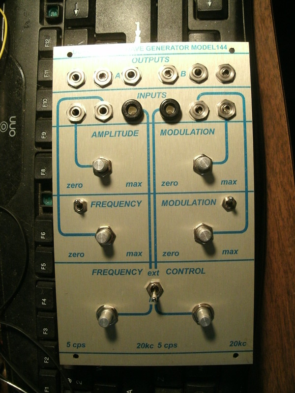
FRONT PANEL ARTWORK:
TROUBLE-SHOOTING:
-If you get no audible output from an oscillator but the voltages check closely around the core with one that works, check on an oscilloscope to see if it's oscillating at supersonic frequencies. I had a bad IT122 doing that and a quick swap solved the problem.
-Generally, the oscillators may not oscillate upon first power-up due to trimpots being out-of-range. (If you can touch the IT122 and U147 metal cans and hear no buzz through the audio output, you are out-of-range.) The third trimpot going to the U147 through a 22K resistor is the one to try; sweep it until you hear a small crunch/puff of noise then oscillation; when past that point, sweep the first trimpot to 5Hz.
MODIFICATIONS:
-I had thought that soldering the CV input wire/signal path to the Frequency pot center lug, which goes to the CV control input on the PCB, would work, and it doesn't enough to recommend sticking with an internal/external CV switch to go between the front panel pot and the CV input banana jack. I might do a revision with a simple opamp CV mixer per channel, as CV response isn't a deal-breaker in regard to the sonic character.
-Extreme FM: Bypassing the 47K resistor on the FM input provides for greater depth of modulation. Can be done via a switch on the front panel. You may have to use something like 1K instead to avoid continuous bleedthrough/modulation.
-VCAs for Modulation paths. Fit a quad 110 Gate PCB behind this and use them to add VC to each of the four Modulation input paths. The front panel potentiometers would simply be 10K or so pots wired to +15V and ground with the center lug to the VC input per Gate. A banana jack tied to the center lug to VC adds external control. BUT:
Any type of VCA would work here, to have CV open and close a VCA feeding either the FM or AM inputs. Note that there may be bleed on the FM path because it's not a pot resting at ground (no signal) at minimum settings. Any bleedthrough on the VCAs part and you'll have continuous, unwanted modulation. There are modern VCAs such as those based upon the 2164 IC which will likely have better performance for that purpose...but those have drawbacks as well (having to use all four VCA cells to provide a pair of VCAs with exponential response, requiring two boards for four independent VCAs, etc.) Thanks for the kind words. And please note that the "extended" 144 shown at the build page didn't quite work out...you have to use something like a 156 to mix/sum CV to it; you can't just attach the CV in jack to the Frequency pot and route it to the PCB. Buchla's 200 series oscillators incorporated CV mixing and processing into the circuit behind the front panel...
1V/Octave may be possible through selecting the appropriate resistor at R5 (factory = 220K). (This mod is untested for U147 users.)

Right: Standard 144. Left: Extended module featuring sawtooth waveform outputs, switched extreme FM, switched silver mica (factory) and styrene timing caps, and a 110 Quad Gate board for voltage control of all AM and FM signal path indexes. That didn't work out due to the 110 having a slight bleed which is fine for audio duties (really low) but when audio-rate FM is concerned, no go.
Build of the provided etch artwork. Note the two large 1/2W 2R2 resistors at the power input.
EXPECTATIONS:
This is a great-sounding oscillator and the sawtooth wave addition is quite nice. However, I'm not yet certain that there is any tracking possible with it other than an arbitrary scale, so do not expect the two oscillators to follow each other very well at all, and know that to have them track in unison tuning melodically, you'll need to use CV controllers which provide separate control and output rows, one per oscillator, to tune every set of notes.
POWER:
Ground and +15V.
PARTS:
The matched, dual transistor IT122 or ITE122 or LS122 is used here as is also used in the 110 Gates and 111. A matched pair of 2N3904 (?) may suffice as replacement. The 122 is much more closely matched than the MD708B which is used in the 158 Dual Sine-Saw Generator.
2N3391A, also used in early Moog Modules, is currently $0.58 at Mouser.com. 610-2N3391A. The trace layout accommodates its ECB pinout. Fairchild's version (obsoleted) shared the same pinout.
2N3565 may possibly be substituted with 2N3904. There is one matched pair per oscillator, for gain (Hfe).
2N4916, 2 per oscillator. 2N3906 may possibly function here. Untested.
2N5020 at mouser.com, 2 per build, to replace U147. Mouser part 106-2N5020
The timing capacitor was originally a huge Mallory polyester type. It looks to be the .0022uF near the second 2N4916. I've provided solder pads for a few variations depending upon taste, including 5mm for box-type caps, 14mm for polystyrene (or polycarbonate as is used in all other Buchla timing cores), or perhaps even very large .0022uF Silver Mica.
There are tantalum capacitors used in the signal path on the original. Elna Silmic II "audio" type capacitors, as well as Nichicon "Super Through" (which may not be available in small ratings) and Panasonic FC electrolytics may be substituted for a potentially different sonic character. The two 15uF tantalum per oscillator (4 total) are provided for in SMD form and live on the bottom / solder side of the PCB.
Five FD111 silicon diodes are listed but I've been unable to source any. The 1N4148 is listed as a potential substibute, as well as BAW62, BAW76, and BAX95. 75V, faster than 5ns.
Eight 1K 6mm multiturn trimpots, although standard 3/8" trimpots are possible here. Inline footprint.
Carbon Composition resistors, 1/4W. There is contention regarding their use in such circuits with though running along the potentially true and logical conclusion that Don used these because of availability and perhaps pricing compared to other types. Some people say these are slightly noisier than carbon film and metal film and that their "magic" only occurs when they are driven at very high voltages, producing a 2nd Harmonic distortion. Others will seek non-magnetic tantalum resistors such as Audio Note and Takman brands or Vishay 1% non-magnetic types. Some will stuff this unhesitatingly with 1% metal film. For those interested in coming as close to the original, Mouser and other component houses carry Kamaya and other brands of modern CC 1/4W types, 5%. Note that for those resistors which were 10% in the original, this is an immediate doubling of accuracy. Vintage AB resistors rise in value with age so they may now be outside of the generous 10% definition.
It would seem to me that a system 100, stuffed with all 1% resistors, would be pretty damn boring in terms of actual use / interaction.
BOM:
Transistors:
2) IT122 or ITE122 or LS122 from Linear Systems, or perhaps matched 2N3904 or similar.
4) 2N4916
12) 2N3565 or perhaps 2N3904, matched pair per generator for Vbe
2) 2N3391A, Mouser 610-2N3391A
2) 2N5020 in place of the U147. Mouser part 106-2N5020
2N3565 and 2N4916 are available at unicornelectronics.com.
Capacitors:
2) 47pF ceramic disc
2) 100pf ceramic disc
6) 910pF ceramic disc or film. .001 may substitute.
2) .001 ceramic disc or film.
2) .0022uF polyester or any film or silver mica*
2) 1uF tatalum
4) 15uF tantalum SMD, Mouser 74-TR3D156K035C0150
2) 56uF tantalum, Mouser 80-T322E566K015AT, $4.00 each. Or, 56uF Elna Silmic II or equivalent electrolytic type.
*The original were large Mallory PVC 600V polyester film caps. The modern equivalent are "Orange Drop" types, available at Mouser or Small Bear.
10) FD111 diodes, substitute indicated as 1N4148. Perhaps match the pair per generator at the matched 2N3565.
Resistors:
5% 1/4W carbon composition (Kamaya, etc.) unless noted:
2) 470r
10) 4K7
6) 47K
2) 220r
12) 2K2
6) 22K
2) 220K
2) 1K
18) 10K
2) 1K5
4) 15K
2) 2R2 1/2W
Use of 5% carbon film resistors is fine.
Carbon Film 5%, 1/4W:
2) 900r
4) 3K6
2) 330K
Trimmers:
8) 1K 6mm or 3/8"
Potentiometers:
2) 10K linear for Frequency Control
4) 50K audio for Frequency Modulation and Amplitude Modulation
Hardware:
8) Tinyjax
2) Black banana jacks
Switch for Internal / External CV Control:
1) Panel-mount DPDT, Mountain or CK
ORIGINAL SCHEMATIC:
http://electro-music.com/forum/phpbb-files/buchla_1440_1_200_137.jpg
My build does not include one trace, the one from the right side of the IT122 to +15V.
ETCH ARTWORK / PARTS LAYOUT:
The parts legend is wrong; it's a view from the solder trace side.
Etch artwork...click here to download the PDF file.
POWER CONTINUITY:
Coming soon. +15V goes around the outside and ground goes up the middle.
Build:
Note that the "D" case tantalum SMD 15uF capacitors go on the bottom/trace side of the PCB. There are two 2R2 1/2 watt resistors on either side of the +15V input, with the 15uF bypass capacitors on the opposite side.
Note that for use with the 2N5020 FET, you need to replace the 220K resistor at the FR solder pad with a 110K or 120K.
The above build includes extra audio outputs, for the sawtooth core, as well as switching for FM depth.
An extra set of ground pads are provided on the PCB to go to the ground lug of any of the audio jacks; only one is required.
An extra pair of solder pads for the +15V rail are provided at each corner after the power inputs. Solder one of them to the required +V on the Frequency pots.
-The AM solder pad on the PCB is connected to the AM pot per the schematic.
-The FM solder pad on the PCB....etc. as above.
-The Fr solder pad is wired to the center lug of the DPDT switch which selects Internal or External CV
-The Out pads are wired to the inside pair(s) of audio output jacks.
-The Saw Out pad can be ignored or wired to front panel audio jacks.
CALIBRATION:
The following calibration procedure does not apply to builds using the 2N5020 JFET.
Generally, the oscillators may not oscillate upon first power-up due to trimpots being out-of-range. (If you can touch the IT122 and U147 metal cans and hear no buzz through the audio output, you are out-of-range.) The third trimpot going to the U147 through a 22K resistor is the one to try; sweep it until you hear a small crunch/puff of noise then oscillation; when past that point, sweep the first trimpot to 5Hz.
AM: Set an oscillator to minimum frequency and patch one at some medium frequency into its AM input. Increase the amount pot to maximum. Trim until there is no sustaining tone between the obvious square wave "on"s. Repeat on the other oscillator.
Scaling: A friend recorded an original 144's pitch response to several voltages.
At 2 volts, it produces G0, 24hz.
At 4 volts, it produces E3, 164hz.
At 6 volts, it produces a very flat D4.
At 8 volts, it produces a very slightly sharp Db6.
It appears to wish to be E3 through E6, from 4V to 8V, which is 4V = 3 octaves.
Procedure:
-Set the initial frequency via R10, the bottom trimmer, to 5Hz (five ticks per second) with no external voltage present.
-Input 8V to the input. Set trimmer 3 (R18) for 1318Hz, or E6.
-Input 4V. Set trimmer 2 (R4) for 164Hz, or E3.
-Repeat until acceptable. If you wish, now set R10 for 5Hz, but check to see if the front panel Frequency pot will sweep it out beyond audibility after having done so.
It is certainly easy enough to scale yours to what the vintage unit produced, if wished.
I've confirmed that with the U147 FET per the original, this can be set to operate with 10V CV ranges (later 200 modules/200e modules) by using 110K resistors in place of the 220K at the Freq input, and calibrating it as above but to have a 6V input produce 1318Hz.
Procedure for U147 versions optimized for 10V CV/ Euro:
-Same as above but input 6V for 1318Hz.
-This requires a 110K resistor at the CV input versus the stock 220K.
FRONT PANEL ARTWORK:
TROUBLE-SHOOTING:
-If you get no audible output from an oscillator but the voltages check closely around the core with one that works, check on an oscilloscope to see if it's oscillating at supersonic frequencies. I had a bad IT122 doing that and a quick swap solved the problem.
-Generally, the oscillators may not oscillate upon first power-up due to trimpots being out-of-range. (If you can touch the IT122 and U147 metal cans and hear no buzz through the audio output, you are out-of-range.) The third trimpot going to the U147 through a 22K resistor is the one to try; sweep it until you hear a small crunch/puff of noise then oscillation; when past that point, sweep the first trimpot to 5Hz.
MODIFICATIONS:
-I had thought that soldering the CV input wire/signal path to the Frequency pot center lug, which goes to the CV control input on the PCB, would work, and it doesn't enough to recommend sticking with an internal/external CV switch to go between the front panel pot and the CV input banana jack. I might do a revision with a simple opamp CV mixer per channel, as CV response isn't a deal-breaker in regard to the sonic character.
-Extreme FM: Bypassing the 47K resistor on the FM input provides for greater depth of modulation. Can be done via a switch on the front panel. You may have to use something like 1K instead to avoid continuous bleedthrough/modulation.
-VCAs for Modulation paths. Fit a quad 110 Gate PCB behind this and use them to add VC to each of the four Modulation input paths. The front panel potentiometers would simply be 10K or so pots wired to +15V and ground with the center lug to the VC input per Gate. A banana jack tied to the center lug to VC adds external control. BUT:
Any type of VCA would work here, to have CV open and close a VCA feeding either the FM or AM inputs. Note that there may be bleed on the FM path because it's not a pot resting at ground (no signal) at minimum settings. Any bleedthrough on the VCAs part and you'll have continuous, unwanted modulation. There are modern VCAs such as those based upon the 2164 IC which will likely have better performance for that purpose...but those have drawbacks as well (having to use all four VCA cells to provide a pair of VCAs with exponential response, requiring two boards for four independent VCAs, etc.) Thanks for the kind words. And please note that the "extended" 144 shown at the build page didn't quite work out...you have to use something like a 156 to mix/sum CV to it; you can't just attach the CV in jack to the Frequency pot and route it to the PCB. Buchla's 200 series oscillators incorporated CV mixing and processing into the circuit behind the front panel...
1V/Octave may be possible through selecting the appropriate resistor at R5 (factory = 220K). (This mod is untested for U147 users.)