Many thanks to the good gent who documented his vintage 175 module for this project. Oddly, I've had to change the circuit from what was shown on his actual module...have sent him this prototype for comparison; will comment if any differences are detected.
This is a discrete, dual equalizer module with bass cut/boost and treble cut/boost per channel (two channels). No opamps. Very useful for shaping the input or output of the 190 dual reverberation module or for general tone shaping. It is unknown why EQ is not a regular function in all modular synthesizers. It is extremely useful for tone shaping in addition to filters, etc.
It is also known as a line driver module as it has a strong output. It should be able to drive headphones (if you wish to use it for such I'd recommend adding a dual audio pot as a volume control at the output of the circuit and of course an appropriately-sized headphone jack). My earbuds show it to have the same output level as the square output on a 144 clone, or apparently unity gain. The 144 causes the 175 to clip a bit when adding full bass boost.
Although the layout is optimized to mount the potentiometers directly to the PCB, if is certainly possible to stack two of these PCBs with standoffs and hand-wire to front panel pots for a quad module, or to add this PCB/circuit to another module build requiring EQ.
POWER:
+15V and ground. +12V would likely work.
SIGNAL LEVELS:
The 100 series is optimized for 1V signals.
PARTS:
4) 2N3565 or 2N3904
2) 2N4916 or possibly 2N3906
2) 2N3566 or possibly a BC550C with an Hfe of 500 or so
All of the above types are available at unicornelectronics.com.
4) 100uF 35V Elna Silmic II audio-grade capacitors
4) 10uF 50V Elna Silmic II audio-grade capacitors
1) 2200uF electrolytic capacitor, Mouser
1) 47r
4) 2K2
2) 10K
6) 6K8
2) 68K
6) 330r
4) 15K
2) 100r
2) 3K3
2) 33K
12) 1K5
Thanks to Mike S. for getting the resistor BOM in shape!
Optional: The 100r, 10K, 2K2, and 47r can all be carbon composition type resistors if you wish.
2) .0047uF 100V "Orange Drop" capacitors, Mouser
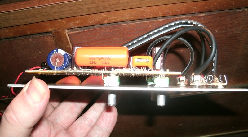
4) .22uF 100V "Orange Drop" capacitors, Mouser have these 400V (as seen in the pics).
These are the core capacitors for the EQ. The "Orange Drop" types are known for sounding good and are fairly easy to acquire; many tube amplifier and guitar parts shops have them. Know they are fairly large and you'll have to bend the leads to work with this PCB.
The original caps were precursors to the "Orange Drop" types, being Mallory polyester types often seen in the Buchla modules (huge, cabernet-colored types he must have gotten in quantity from his aerospace connections).
Pots are unknown; my prototype uses 250K linears. I've just completed the prototype pictured with 1M Audio taper and can confirm, =use linear taper=. 250K should be good. 1M is also just fine. I haven't tested to see if 1M provides any greater amount of control range.
A .040" #60 drillbit is used for the Alpha pot stand off and lead holes.
In the event of a water landing, the Orange Drop capacitors double as flotation devices.
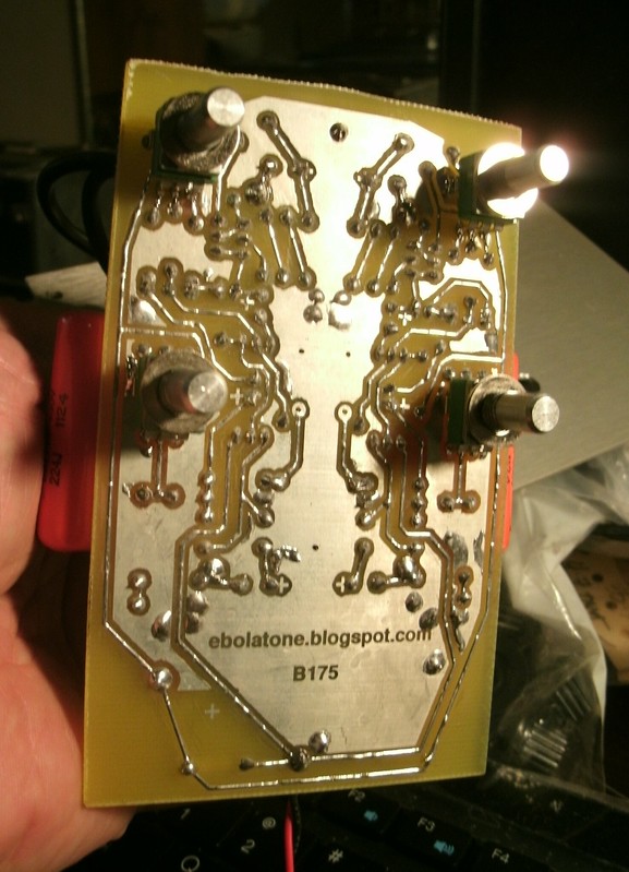
ETCH ARTWORK
Click here to download the PDF file.
CONTINUITY

Note that ground continuity only functions after the installation of the jumpers.
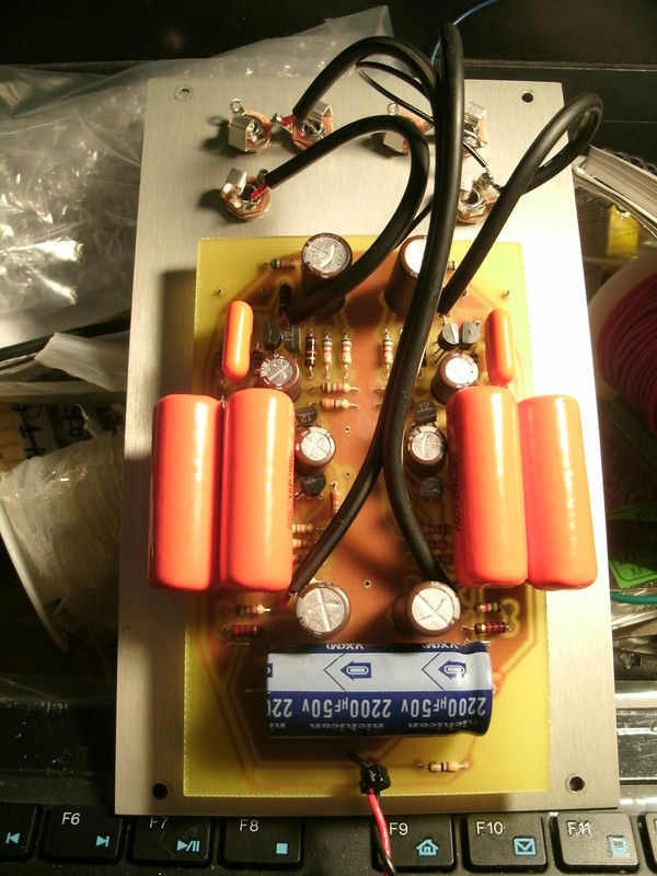
PARTS LAYOUT

Note that the 3K3 with the asterisks (*) at the center are unknown; my second build, pictured here, did not use them so use them if you wish, or not.
Green lines are bare wire jumpers.
ASSEMBLY
-Note that the input/output wires are shielded; ground them at the front panel jacks but trim the shield from the end soldered to the PCB.
-Pots are 1M linear taper Alpha 9mm snap-in PCB-mount types available from mammothelectronics.com and THONK. Some modification is required; please see this post for specific instructions.
-Remember 1mm drillbits (#60) are perfect for the pot leads and standoff pins.
-Note that the potentiometer standoff pins may be soldered onto the PCB; provision is made in the ground areas for such and it causes the pot shaft to become ground.
-Put the finished PCB up to a bright light (behind the PCB) to check the potentiometer soldering for bridging.
-Do a continuity check before powering it up. Bridging may occur to ground while soldering.
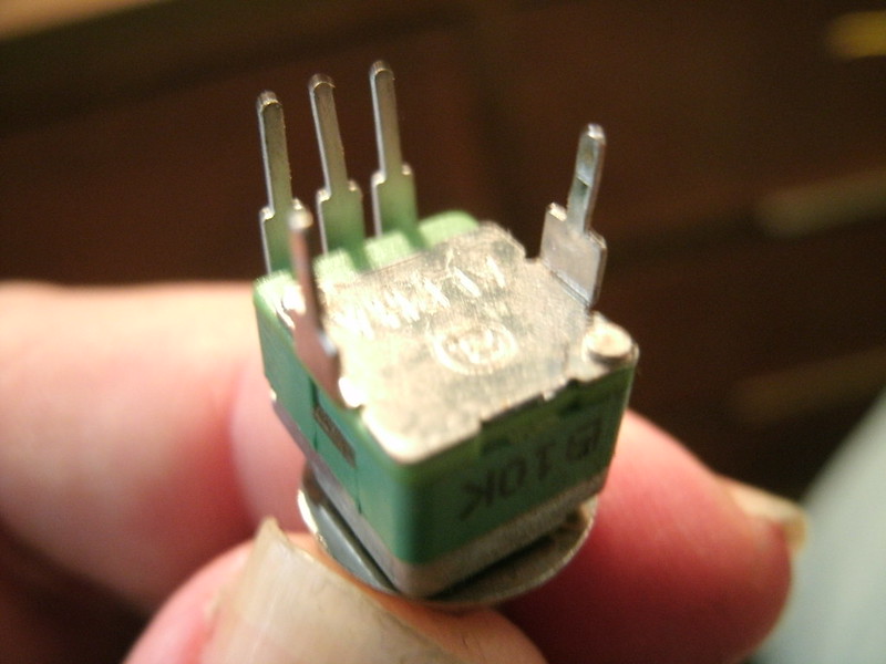
All pots must be modified like this; procedure is detailed in my 156 post.
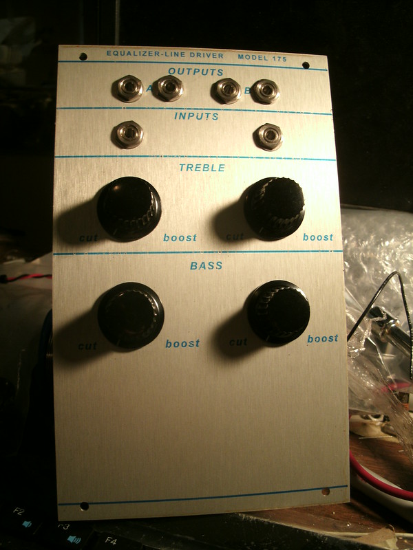
SUGGESTED FRONT PANEL ARTWORK
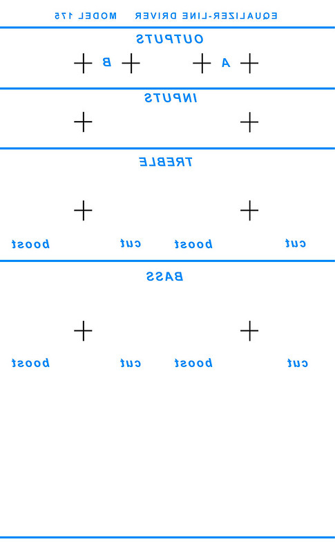
Click here to download the correctly-sized PDF file.