This is a new, confirmed/tested layout of the 106 discrete mixer. A previous version included an ill-fated attempt at adding inversion per channel. This version is per the original schematic only, and adds the convenience of PCB-mount potentiometers.
The main issue with this design is to make sure all of your transistors are matched for gain, all six in the same range, better than 5%.
2N3565 are specified for this circuit but 2N3904 are just fine. Elna Silmic II audio-grade capacitors are fine (100uF 35V, 10uF 50V). The 220r, 2K2, 1K, and 10K may all be carbon composition type resistors if you wish. 5% tolerance carbon film are fine for the rest of the circuit.
Alpha 9mm PCB-mount snap-in 50K audio taper pots are used (6 quantity), available from mammothelectronics.com and THONK. Modifications are required prior to mounting and soldering them to the PCB; please see my 156 Dual CV Processor post for instructions and ordering. Note that three washers on each pot behind the front panel results in a perfect shaft height to support the Davies knobs slightly above the front panel without rubbing. Don't use a washer on the front side, just a nut each, to secure everything.
Power:
+15V and ground.
ETCH ART:
Download by clicking here.
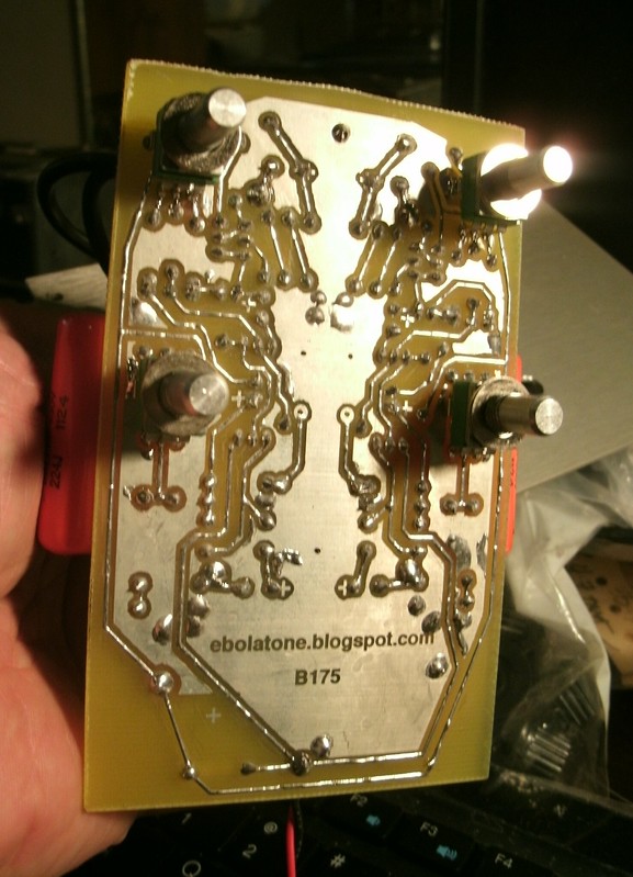
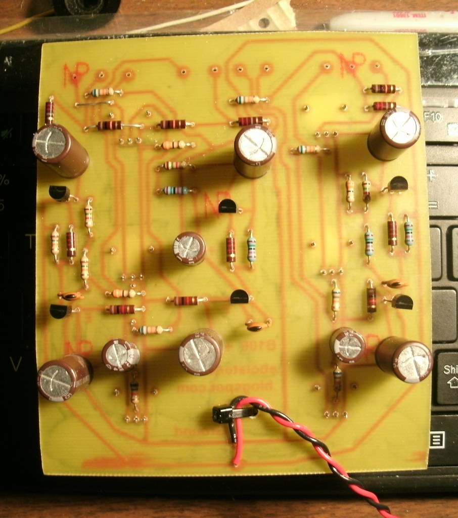
CONTINUITY:
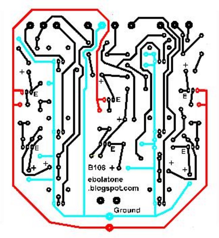
Unsure what happened here; listen to 8-bit electro while viewing this image.
PARTS LEGEND:
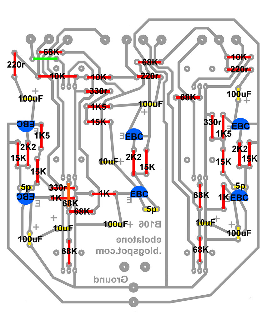
Note the single 68K which is mounted on the trace side of the PCB. The green line is a bare wire jumper.
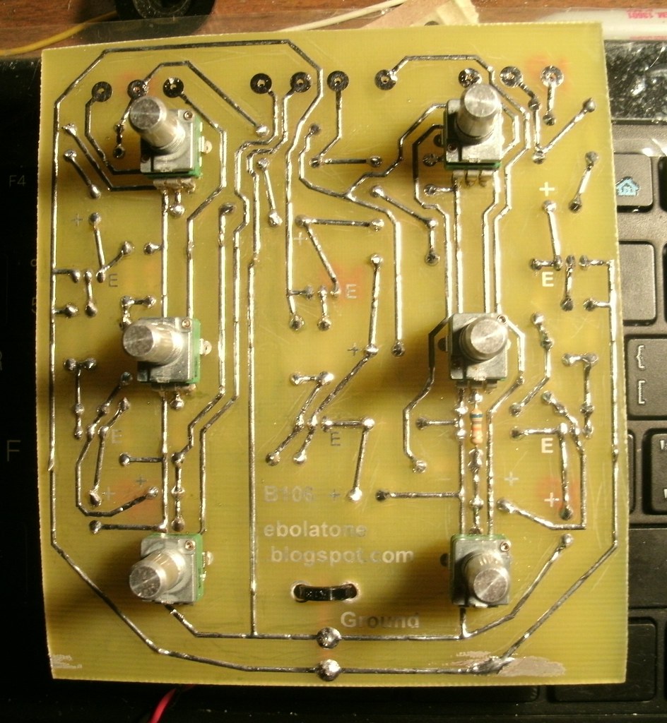
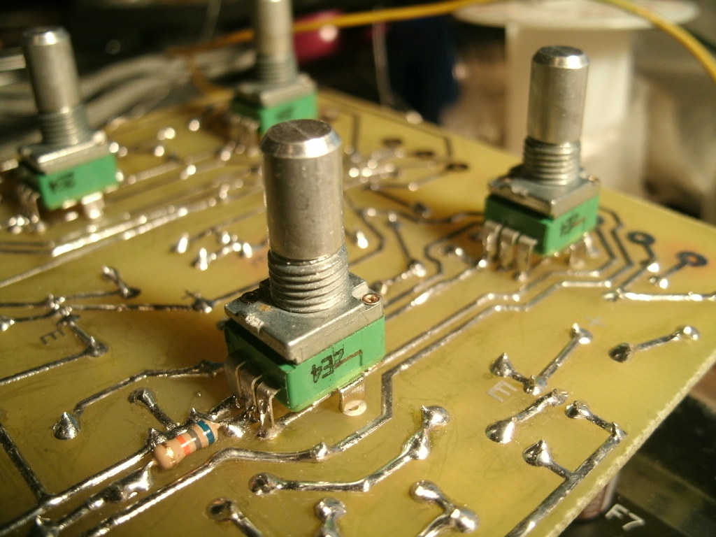
Detail of the trace-side mounted 68K resistor.
A .040" #60 drillbit is used for all Alpha pot holes.
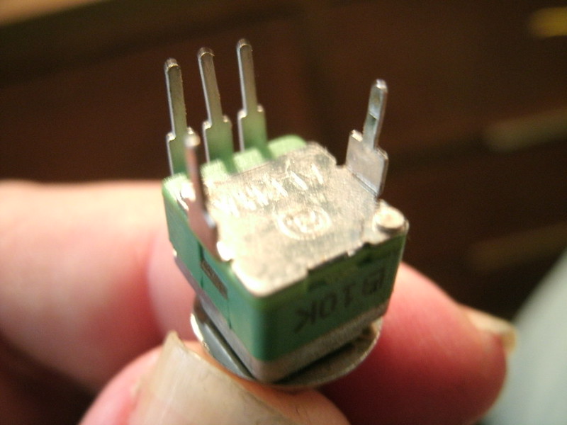
All pots must be modified like this; procedure is detailed in my 156 post.
PARTS:
Here is the original schematic. You'll note some discrepancies between channels. There are swaps between 10uF and 100uF in places. Two versions have different pF range cap values.
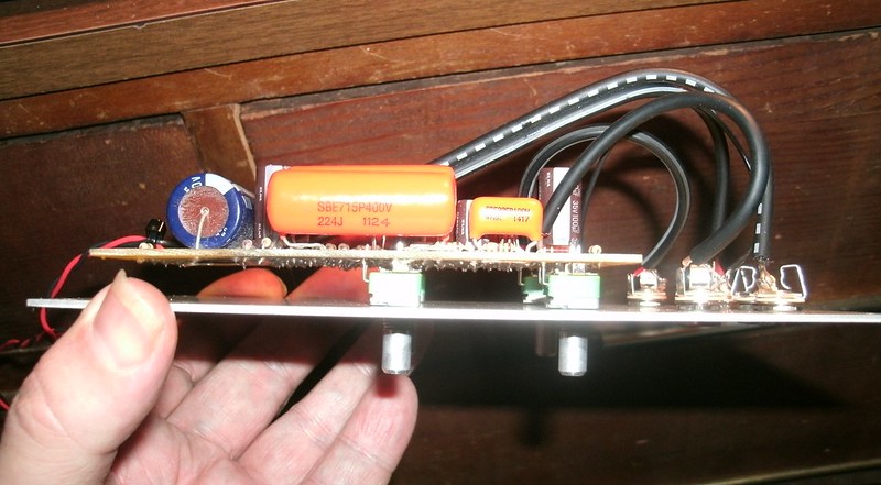
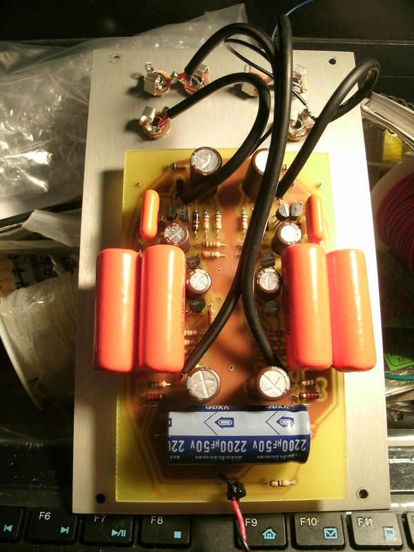
PANEL WIRING:
The wiring pads are beneath their target audio jacks, for the most part.
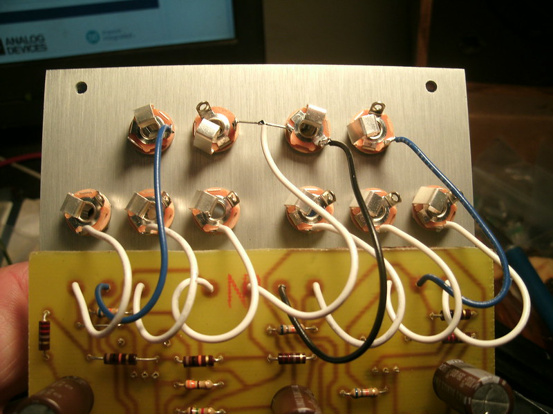
A sharp eye will catch that the left-side blue wire is connected to the ground lug and not the signal. I caught that during testing.
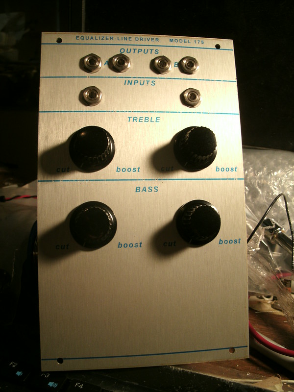
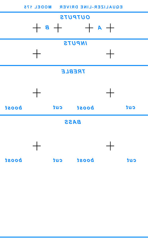
SUGGESTED FRONT PANEL ARTWORK:
This will be a new, better-aligned artwork coming shortly. The old one will be slightly off.
The main issue with this design is to make sure all of your transistors are matched for gain, all six in the same range, better than 5%.
2N3565 are specified for this circuit but 2N3904 are just fine. Elna Silmic II audio-grade capacitors are fine (100uF 35V, 10uF 50V). The 220r, 2K2, 1K, and 10K may all be carbon composition type resistors if you wish. 5% tolerance carbon film are fine for the rest of the circuit.
Alpha 9mm PCB-mount snap-in 50K audio taper pots are used (6 quantity), available from mammothelectronics.com and THONK. Modifications are required prior to mounting and soldering them to the PCB; please see my 156 Dual CV Processor post for instructions and ordering. Note that three washers on each pot behind the front panel results in a perfect shaft height to support the Davies knobs slightly above the front panel without rubbing. Don't use a washer on the front side, just a nut each, to secure everything.
Power:
+15V and ground.
ETCH ART:
Download by clicking here.
CONTINUITY:
Unsure what happened here; listen to 8-bit electro while viewing this image.
PARTS LEGEND:
Note the single 68K which is mounted on the trace side of the PCB. The green line is a bare wire jumper.
Detail of the trace-side mounted 68K resistor.
A .040" #60 drillbit is used for all Alpha pot holes.
All pots must be modified like this; procedure is detailed in my 156 post.
PARTS:
Here is the original schematic. You'll note some discrepancies between channels. There are swaps between 10uF and 100uF in places. Two versions have different pF range cap values.
PANEL WIRING:
The wiring pads are beneath their target audio jacks, for the most part.
A sharp eye will catch that the left-side blue wire is connected to the ground lug and not the signal. I caught that during testing.
SUGGESTED FRONT PANEL ARTWORK:
This will be a new, better-aligned artwork coming shortly. The old one will be slightly off.