Saturday, October 4, 2014

Buchla 156 Dual CV Processor DIY

Buchla 156 Clones
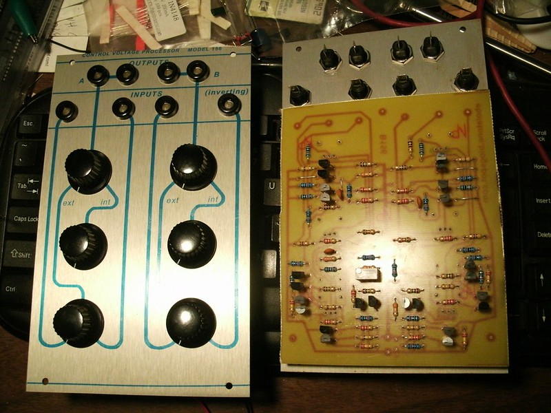
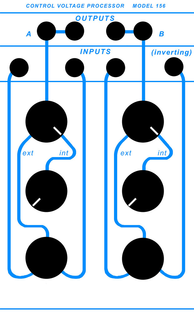
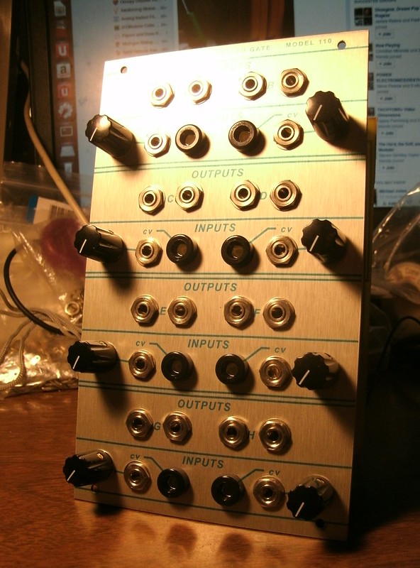
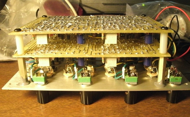
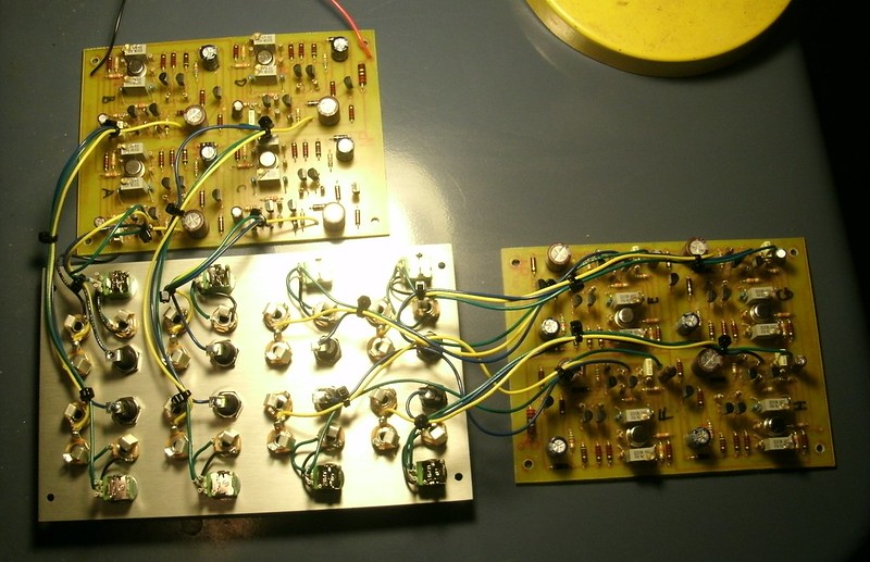
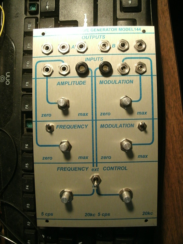
Left, prototype with panel suffering from a bit of Lazertran "stretch"; right, latest edition module in process.  
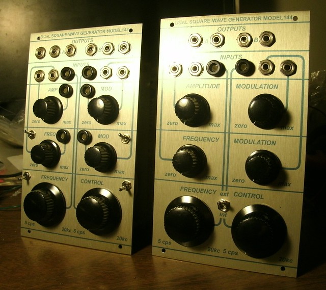
Buchla 156 DIY
Final version.

This is a true clone directly from the schematics.

A good reference for learning and using this module and other 100 modules:

http://manuals.fdiskc.com/flat/Buchla%20100%20Series%20Owners%20Manual.pdf

This module can be essential in using 100 series modules which have only a single CV input jack such as the oscillators, which do not have CV mixing on-board...their front panel Frequency controls are defeated to allow external CV to modulate the oscillator. If you wish to control an oscillator by a CV keyboard or sequencer AND add another pitch modulation effect you'll need to use a section of the 156. The good news is that the 156's center Offset pot then replaces the oscillator's Frequency control, when you set the top 156 pot to the center or so. Of course, the keyboard or sequencer must then be tuned to produce the desired pitches because any fading between two sources will (LIKELY, CHECK) cause compression of both. Haven't fully put this thing to use yet; that's what I'd believe it does in actual use, will confirm. I've never played a 100 system and there are very likely unexpected quirks to be discovered and applied musically...

The two sections, alike but for one difference, allow you to manually mix/crossfade CVs as well as offset them with a 15V range, which of course is standard System 100 voltage. The second (right side) section has an inverting input which flips 0-15V CVs to 15V-0V for contrary motion modulation, etc. The top pot fades/mixes between the external input mixing and an internal offset generator which provides 0-15V. In other words, you can compress an input voltage to 1/4 of its range, for example, and then shift it to vary only around 5V or wherever you wish. You can also use the offset generator alone to manually sweep any CV'd parameter(s).

So in other words, the 156 acts as front panel Frequency control and a crossfade of up to two CV sources if you're using it with oscillators, filters, etc. It is basically what was integrated into the 258 oscillator series: front panel frequency control summed (simultaneously available) with the attenuated CV inputs.

Use with 200 and 200e series modules which produce and expect a 10V CV modulation range should work fine unless you offset things above 10V. I'm not sure what will occur but likely the top 5V will simply get ignored.

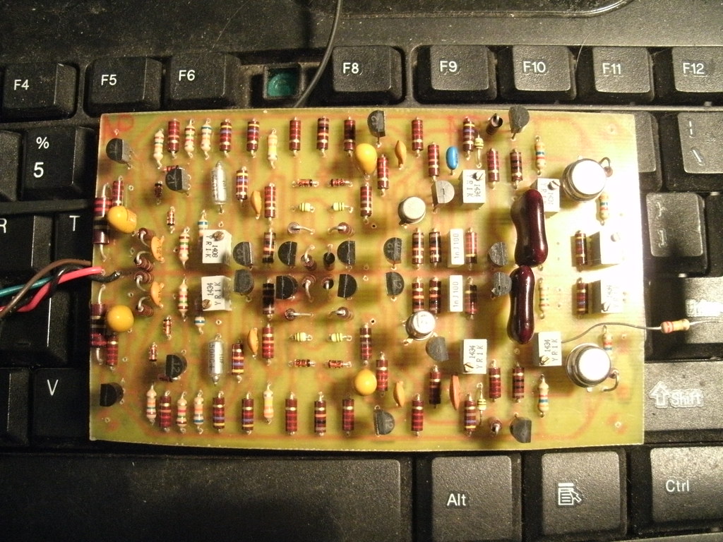
This is not as simple a build as it appears. There are 58 resistors...

There is a caveat in use; the module produces large voltages at its outputs via the external processors when any of them are unpatched/not connected to another module. Sweep the int/ext pot to eliminate this or unpatch the module entirely if not in use. When you patch into it, it settles to near zero volts...weird, but the 144 acts the same way...if you set it to Ext CV, it oscillates at an unexpectedly high frequency until you patch into the CV input..also, there is some stray voltage offset at the outputs even with the inputs set to zero, so expect up to 0.35V or so in actual use.


Requirements:

Ground and +15V power rails.


Parts:

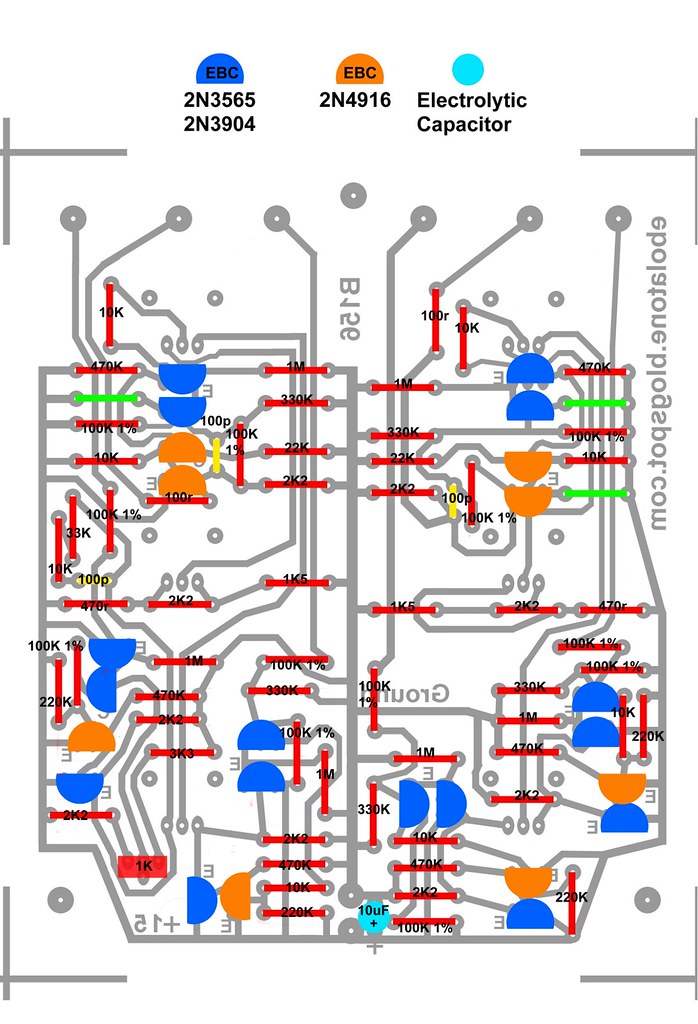
Five pairs of decently-matched for voltage 2N/PN3565, 2% or better is plenty. I've just built one using 2N3904 and it works just fine. (The matched sets are visible in the layout/parts legend as the blue pairs.)
Four unmatched 3565.
Eight 2N4916 transistors. 2N3904/6 might work just fine; I've tested modules using 3904 to replace 3565 and it works well. Haven't replaced 4916 with 3906, however.
BC5XX are also applicable as are equivalent Japanese generic NPN/PNP.

There are no unusual resistor values and I've even eschewed carbon composition for this build. The original used mostly 10% types with some 5% specified and several 1% 100K. Using all 5% carbon film resistors is fine excepting of course the indicated 100K 1%. Using all 1% metal film is also fine, but don't expect this module to be an engine of precision. And that's perfectly fine...

Three 100pF ceramic capacitors with a 5mm pitch (distance between legs). One 10 or 15uF electrolytic capacitor for power smoothing, 35V or more.

The recommended trimpot is a Mouser 858-67WR1KLF. The etch footprint also allows for use of the 858-67YR1KLF. At the time of this writing both are $1.24 each. Not bad for a multiturn trimmer!

Four 10K linear and two 250K linear Alpha 9mm PCB-mount snap-in potentiometers from Mammoth Electronics or from THONK, with the nub already removed. 

Six Davies 1610 knobs. Mouser: 5164-1610AA


Options:

You can hand-wire the PCB to front panel potentiometers of your choice (four 10K linear and two 250K linear per module) or use snap-in PCB-mount 9mm Alpha types, available from Mammoth Electronics and mount them to the PCB on the solder side, and the front panel then directly upon them.

I recommend using three washers on each pot (if you're using Alphas) behind the front panel to lift things to a perfect distance for the Davies 1610 knobs. They'll sit just the right distance from the front panel when you put them all the way onto the shaft that you can simply tighten them down instead of worrying about spacing by hand or other tricks.

Three washers (available at Mammoth as well, in the Accessories/Hardware section) are a touch under 12mm tall off of the PCB. 

There are drill marks on the PCB for three standoffs but I've not yet determined the appropriate height. They may be completely unnecessary as all six pots secure to the front panel.


Schematic: 

http://rubidium.dyndns.org/~magnus/synths/companies/buchla/Buchla_1560_1_200.jpg
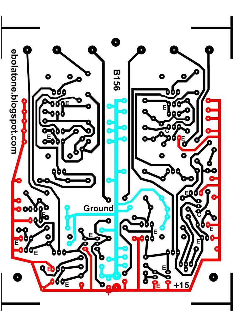

Etch: 

Download the correctly-sized high-resolution PDF by clicking here. One image is reversed for printing upon transparency material for exposing PCBs.
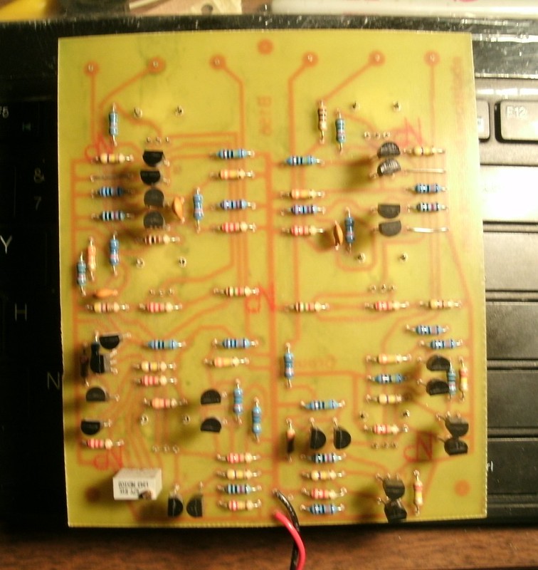

Continuity check:

Buchla 156 5b Continuity


The trace side of your PCB should look like this, not literally meaning the coloration. With a beeping VOM continuity meter, make sure that the positive and ground lines are not bridged and that every point of each has continuity.
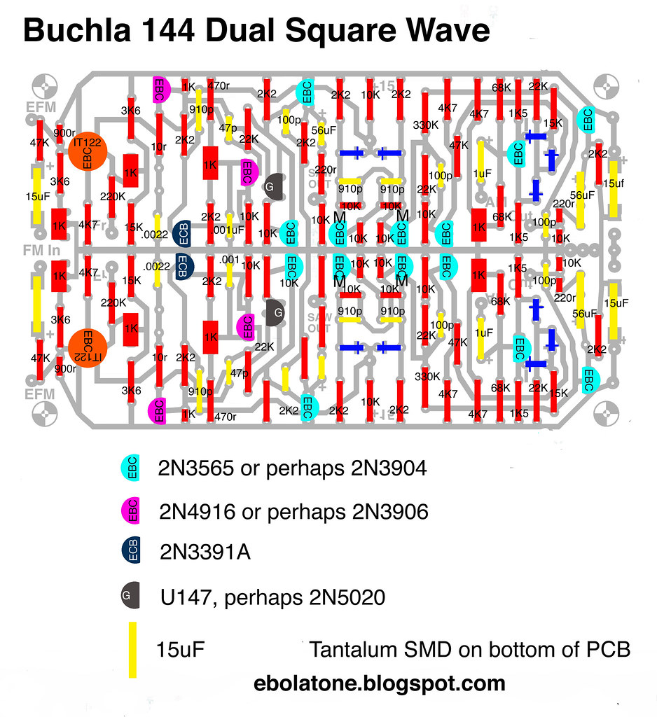


Parts legend:

Buchla 156 5b parts legend


Build:

All holes in the PCB can be done with a #65 drillbit excepting the potentiometers'. Use a #60 drillbit (1mm) for all potentiometer pads.

Solder in all of the resistors first, then the capacitors. Solder the three jumpers. Sorry; I dislike them but couldn't get around having to have three. Now the transistors. Note that the layout is for both types to have EBC pinout. Solder the 1K trimpot. You can use a single-turn top-adjust or a multi-turn type; your choice.

Make sure all of the transistors are correctly installed.

Flow solder on the traces if you wish for reliability, or coat the traces. Deflux the board.

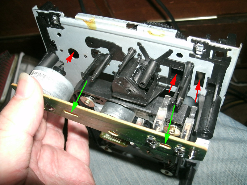
You'll have to make some modifications to each potentiometer as follows:

Alpha 9mm Potentiometer

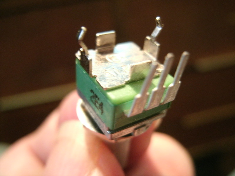
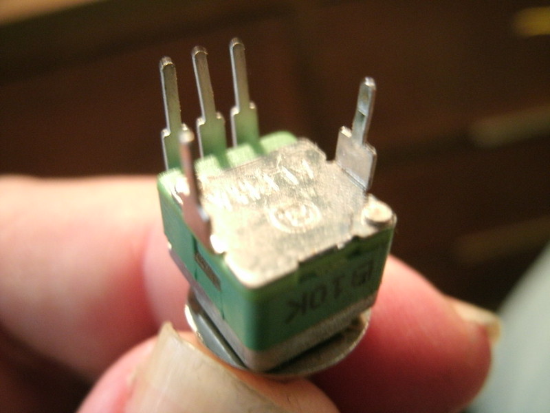
Stock Alpha 9mm PCB-mount snap-in potentiometer, unmodified.

The two spacing tabs need to be removed. This is as simple as grasping each with a plier and rocking it back and forth until it breaks off.

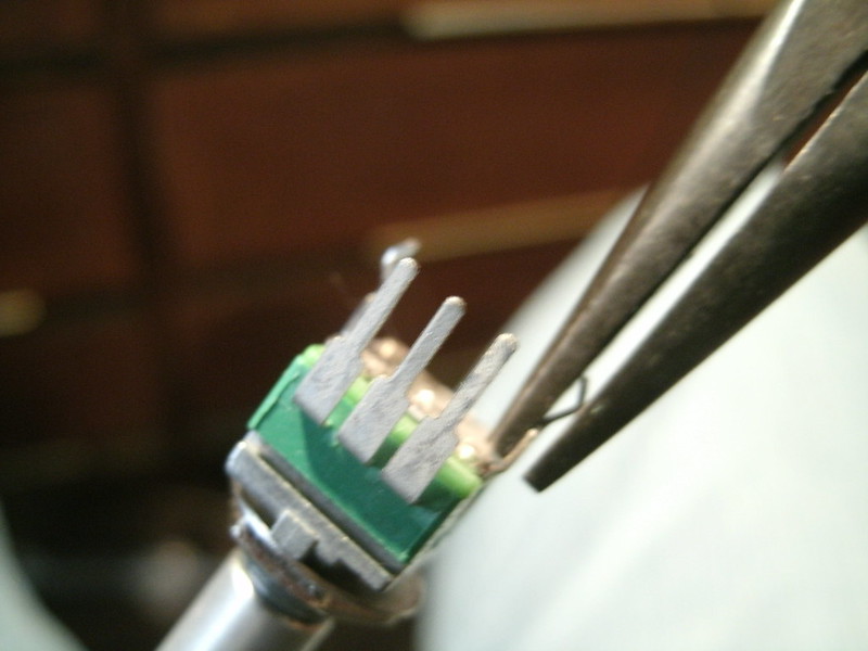
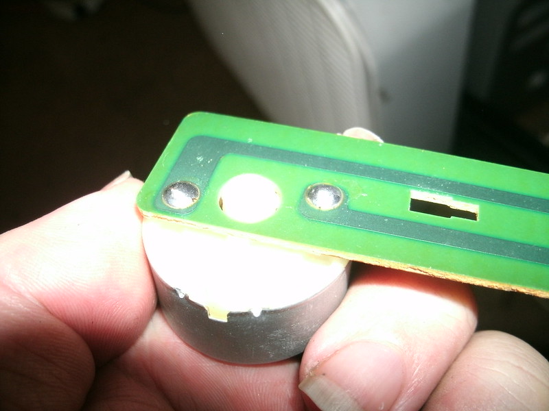
The two mounting legs need to be straightened; simply pinch them with a plier:

GEDC1342


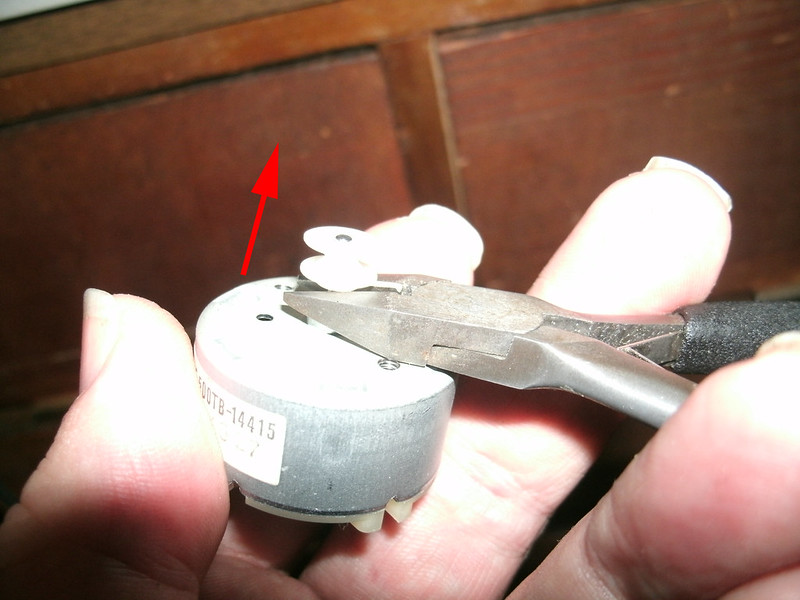
And a metal nub at the front must be removed; a dyke hand tool or a large pliers can take care of this:

Alpha 9mm

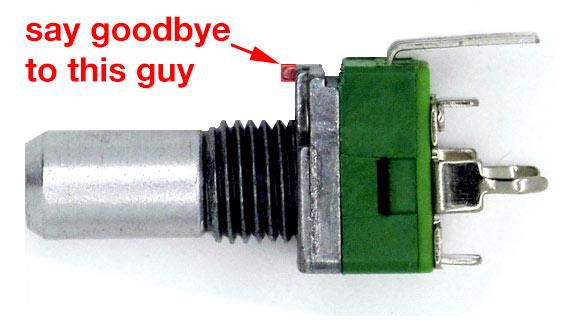
Image via THONK, who sell these with the nub already removed. Thanks!

GEDC1351


GEDC1343

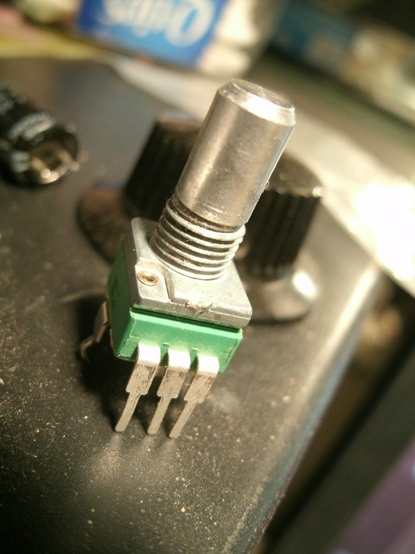
Finished! This is what they'll need to be for this build. 

THONK will be stocking these with the nub already removed:

http://www.muffwiggler.com/forum/viewtopic.php?t=122962

Important note: First solder the rear-most pots (250K) as seen below. The open space in front is required for ease of soldering. Then those in the center, etc.

Mount the potentiometers onto the PCB's solder side. Keeping each positioned well, solder the small pins to the traces. Be careful to not bridge across any of them. It's easy to do so. Test visually and with a beeping VOM continuity meter setting if need be. Remember to keep them nicely perpendicular to the PCB so they'll mount well to the front panel.

Buchla 156 DIY


Untitled
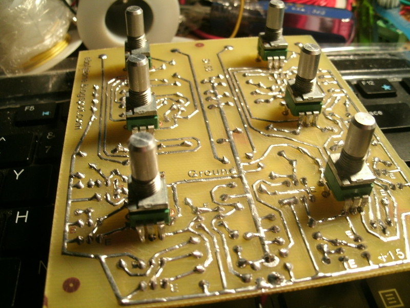
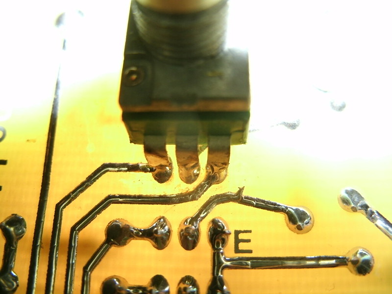
After soldering on the pots, look at the connections with a bright lamp behind the PCB. It's easy to bridge these connections so be sure they're all individual.
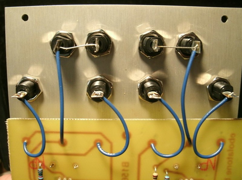


Buchla 156 Clone Wiring
Front panel wiring.


SOLDER PINS BEFORE OR AFTER CHECKING WITH THE FRONT PANEL?

Mount the panel on the pots. Don't forget the three washers on each potentiometer between it and the front panel; this makes the Davies pots sit at a perfect height. Don't use a washer on the front panel side, just the nut.


Suggested front panel artwork:


For visual reference only. Click here to download the correctly-sized PDF. The front panel when drilled should mount perfectly to the potentiometers. There are three pads on the PCB for potential standoff mounting; 12mm might be a touch too short. They are definitely not mandatory.

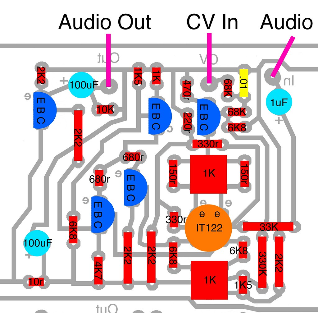
The solder pads directly beneath each banana jack solders to that jack.

IMAGE

Many thanks to Mr. D for the curvy lines!


Testing the build

When you power up the module test it as follows.


156 FP First Cal

Set both top pots fully to Int. Set both middle pots to fully left.

A DC volt meter connected to either set of Output jacks should show something between 0.1V and 0.4V.

Now set the center Offset pots to fully right. Each output should show a voltage around 14.8 volts.

To test the external mixers, set the module as follows.

156 FP Cal Two

Set the left Ext/Int pot fully to Ext. The center Offset pot is thus negated.

Set the right Ext/Int pot fully to Int. The right center Offset pot will be used to indicate correct response. Set it to fully left (0V).

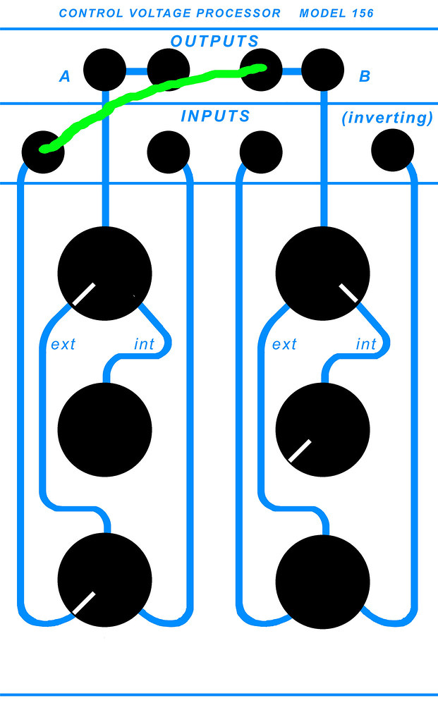
Patch the right Output jack to the left-most Input banana jack. Set the left side's bottom pot fully to the left.

With a DC voltmeter connected to the left section's Output jack, you should see something between 0.1V and 0.4V. If not, you may have a transistor in backwards (I got one wrong and had a 2V reading).

Now turn the right section's middle pot to fully right (15V). The meter should read something around 14.8V.

(Remember that without something patched into the banana jack, the bottom sections will output about 12V each. This is normal.)

Now plug the patch cord from the right section's Output into the right input jack of the left side. Turn the bottom pot fully to the right. Changing the right section's middle pot should produce an around 0V through nearly 15V reading on the meter.

TESTING THE RIGHT SECTION

Set and patch the module as follows.

156 FP Cal Three

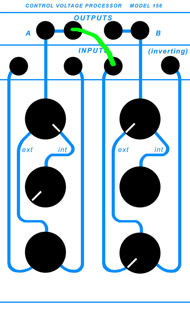
Patch the left section's Output into the right section's left input jack (not the Inverting jack). Set the right section's top pot to fully left (Ext). Set the bottom pot to fully left.

Set the left section's top pot to fully right (Int). Set the left section's middle pot to fully left (0V).

Connecting a DC voltmeter to the right section's Output jack, you should read a near zero voltage (0.1 through 0.4V). Turning the left section's middle pot fully to the right, you should read an increasing value ending nearly at 15V.

If these readings are the case, you are very nearly finished. Now to check the right section's Inverting input, which requires calibration.


Calibration:

There is only one trimpot and it is used for setting the inverting section of the second half.

Set the module as follows.

156 FP Art Calibration

Left section:

-Int/Ext fully to Int.
-The middle pot should be fully to the right (outputs +15V).
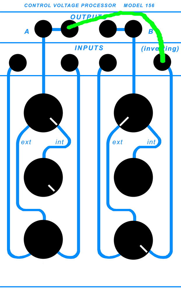
-Patch from the Out of the left half into the Inverting jack on the right.

This allows you to use the left side's center Offset pot to send 0-15V to the right section's Inverting input.

Right section:

-Set the Int/Ext fully to Ext.
-Set the bottom pot fully to the right.

Follow the line from the right side's Inverting input jack to the bottom pot, which is set fully to pass the Inverting input. Setting the right side's Int/Ext pot to fully Ext fully passes that signal path to the output. The line graphics directly represent signal flow, of course. 

-With a VOM reading DC voltage connected to the Output of the right section, turn the trimpot to about 0.3V. It should stop changing around there; set the trimpot for whatever minimum reading you can attain but don't go much beyond it or that will reduce the maximum voltage swing.

-Turn the left section's middle (Offset) pot to the left; the meter should show an increasing voltage with a maximum of greater than 14V but it might not quite make it to a full +15.

In other words, a voltage sweeping from +15V to 0V will output 0V to +15, and of course vice-versa.

If these are your readings, congratulations! You are ready to use your module. Once you've built one of these modules, you'll find the testing and calibration goes by very quickly. 
 

In use:

Buchla 100 gear can be a bit odd when not patched; the 144 dual square wave generator, when switched to External CV modulation oscillates at a fairly high frequency and not its expected minimum of around 5Hz. Patch into the CV in jack, however, with 0V or so, and it will drop to 5Hz or so and sweep upwards from there.


Do you have any aspirin


Saturday, August 23, 2014

Buchla 110 Dual Gate for Euro Format

All related build items and informations are here:

http://ebolatone.blogspot.com/2014/02/buchla-110-quad-gate-diy-build.html

This is an untested edit of the Quad 110 artwork, cut down to possibly work in Eurack format. I don't have art for a Euro power header. This build only uses +15V and ground, the large pads at the edge of the board...remember that this expects +15V CV to fully open, and is happiest with about 2V audio signals, and will output at that level as well, requiring a make-up circuit for the outputs. You should be able to use the input attenuators to set Euro signal levels to where this circuit is happy.

I'm told by a builder that this circuit works just fine with 12V supplies!

Replace R8, 68K, at the CV Input pad, with a 33K or so to use with 200e and later 200 system modules and clones which output 10V CV signals.

NOTE THAT FOR THIS ARTWORK, THE ERROR IN POWER CAPACITOR (100uF DIRECTLY NEXT TO THE SOLE 10R RESISTOR) POLARIZATION HAS BEEN CORRECTED. STUFF THAT PART PER THE "+" INDICATOR ON THE PCB ARTWORK. THE "+" INDICATOR SHOULD ALWAYS LEAD TO THE "+" POWER RAIL, NEGATIVE CAPACITOR LEAD TO THE GROUND RAIL.

Click here for PDF artwork from which to etch.

Ugh, don't know where those random dots came from. I haven't etched from this, it's untested, but if the dots don't cause bridging, this should work. Must be bitmap vs. grayscale.

Remember to set all trimpots to 500r before soldering them in; it will save you a great deal of time in the calibration procedure. 

Thursday, August 7, 2014

Fixing a Cambridge 640C V1 CD Player

Found one of these at a church yard sale when I lived in South Central LA. A dent at one corner shows it to have fallen from a height...didn't play discs, made mechanical noises. The net is full of stories about these developing a "no disc" or similar error.

This was four years ago. During that time I've replaced the laser mechanism thanks to very clear instructions found on the net, but it didn't work. It looked like it needed to be replaced... I've since noted comments regarding a "solder blob" often found on laser mechanisms which protect them during shipping from electrostatic damage. Today, opened it up again and watched a video on youtube on the subject, which helped me to locate the offending party on this one. It's on the far right:

Cambridge 640C electrostatic protection laser solder blob


Removed it and voila, the player plays! The drawer mechanism was still shot, but it's progress! Gave it to a music-loving friend who has less than I do...and it also needed a replacement pully band for the drawer motor, as the original had become stiff. I got a few bands from mcmelectronics.com and one fit, I'm not sure of its size. I've found the items I ordered and only this part number appears to have been used:

42-1050   mcmelectronics.com

Recommending that anyone with one of these players replace theirs as well. I don't believe it's a perfect fit but it appears to be close enough for now.


Fixed the tray drawer issue; it wouldn't fully extend or close. Figured the motor needed replacing and it was indeed as simple as that. Got one from eBay for $5.00...it's an RF-500TB-14415. Easily available, apparently used in more than one place for the same duty. 

To replace it, follow instructions on the net regarding opening the unit (Torx screws, IIRC) and removing the entire laser/drawer (tray) mechanism. Lift the entire mechanism from the case, gently. 

Note the two small connectors to the PCBs; they are different sizes and can't be mistaken/swapped. The ribbon which connects to the laser on the bottom is the same... Note the washers which sit beneath the rear of the tray assembly to slightly tilt the entire thing and that the two screws holding the tray mechanism to the case there are longer than the two which do so at the opening in the front for the tray. Now to remove the tray...

You have to power the unit up and make sure the tray is extended (manually if necessary) before you can get to all of the screws. Make certain you do not short out anything or worse, come into contact with the deadly voltages present inside the unit at points. Do not force the tray all the way out of the assembly, it will break. When the tray is fully extended, power off the unit and disconnect the power cord. 

There are two tray release mechanisms, indicated by the red arrows (the tray is of course already removed in this example: 


Cambridge 640C drawer motor

Use a pair of very small screwdrivers, inserted into the holes at the end of the arms, and pry them out away from the tray on each side, simultaneously. With these pulled outward, you may then slide the tray fully out from the assembly.


The motor is on a PCB beneath the tray, and it also houses the two microswitches. This is what you'll see when it's fully removed:

Cambridge 640C tray motor PCB top microswitches

Note that the sticker with the text faces this direction when mounted correctly (it's possible to reverse mount it but that might cause damage or short it completely; not recommended to find out). 


To remove the motor tray PCB first unscrew the two screws indicated by the green arrows and remove the rubber belt. Set them aside where you'll easily remember them.

Cambridge 640C drawer motor

Cambridge 640C tray belt

There are two plastic teeth which secure the motor tray PCB to the assembly, indicated by the green arrows. On the bottom of the PCB, pinch them together slightly and they will release:

Cambridge 640C tray motor PCB mounting


With the two motor screws and the pulley belt removed, releasing those two plastic teeth will allow you to pull the entire PCB away from the tray assembly. 

Microswitch problems are another item I've read about on the net so make sure to not bend them during this entire process.

After removing the tray motor PCB, heat and remove the solder at the two points which hold the motor to that PCB:

Cambridge 640C tray motor PCB


Remember the orientation for the new motor as shown in an image above. The sticker/text should be visible as shown. 

If your replacement motor came with a piece of plastic for the pulley belt it might not be the correct size to go through the mounting hole in the tray assembly. Also, if it is new and unused it should have a bare shaft. Remove the white pulley disc from the old motor. If it will not release and requires more convincing, I used the bottom side of a wire clipper and gently pried it up off of the shaft, go slowly so as to not break it. 

Cambridge 640C tray motor

Re-mount the motor using the photo used to release the PCB. Make sure the plastic teeth come through the mounting holes on the PCB and snap into place, and that the microswitches go into and through their respective positions, taking care to not bend or displace them as you do.

Screw the motor to the tray assembly and replace the pulley belt per an above photo. You are ready to reconnect the laser ribbon and the two connectors and again, taking care not to short out anything or get into the power supply voltages, power up and test the open/close function. Should work perfectly!

When re-mounting the tray assembly be sure not to forget the two washers which go to the rear of the tray, between the legs through which the screws go and the case. You should be good to go!


If it does not work, I read an article on the net from someone who found that the circuit which drove the motor on his had gone bad, so check this link. 


Further reading:

Replacing the electrolytic capacitors in the analog output section supply and the clock's capacitor


The Lampizator website also indicates that replacing all of the output electronics with Elna or similar audio grade electrolytic capacitors will definitely make a difference...how about if you hack it with the Lampizator circuit itself!


Saturday, July 19, 2014

Buchla 258B Clone Special Edition


Home-brew Lazertran front panel with added graphics for Waveform switching and FM depth...

* Clone of the vintage 258 version B module from the original schematic using original components (uA726, PN3565, 2N4339, 2N4248, 741 opamps, 2N4341, (modern) carbon composition resistors where specified in the schematic)
* Switchable between original module's audio-rate FM depth and extreme FM
* FM depth switch has a center OFF position so you can switch in and out extreme amounts of FM at will
* Normal'd / interrupting FM input jacks (oscillators will FM each other simply by increasing the FM Amount control, no patching required. Any patch cord inserted into the input jack interrupts that Normal and the patched signal will then modulate that oscillator. The sine/alt waveforms are what are Normal'd.)
* Waveform switching per oscillator for the alt wave, Saw or Square
* Gray "Keyboard" in jack, calibrated for 1V/Octave-ish. Should also be possible to trim for 1.2V/Octave response.
* Waveform CV in jack calibrated for 10V signals (later 200 modules, 200e systems)
* Triangle waveform audio output, single output jack on the left
* Both CV inputs per oscillator are twice as sensitive as the factory version for more extreme modulation effects
* EDAC power connector
* Switchcraft Tinijax
* Cardas Tri-Eutectic audiophile solder used throughout the PCB and flowed onto all traces for reliability; used in most of the front panel connections.


1. Detuned saw waves at unison.
2. Detuned square waves at unison, then detuned, then tuned and fine tuned to an octave apart.
3. Both sine waves, playing with original module depth exponential FM.
4. Monitoring one sine wave and FM'ing it by sine, saw, and square waves at the factory module's FM depth. Then sine modulating at Extreme FM depth. Change that wave to square. Goes out to pitched noise.
5. Pitched noise via Extreme FM cross-modulation. Monitoring only one oscillator.
6. Pitched noise via Extreme FM cross-modulation. Monitoring only one oscillator.

Here is a track using a vintage Buchla system with a pair of 258B dual oscillators, doing lots of their characteristic FM, if you need something more musical regarding their tone...

Impart / Tangent

Was considering trying a TEMPCO switched mod; maybe next time. Was concerned about going "too far" and having too many front panel switches. Have not confirmed whether this idea would bear fruit.

Clarity: There were three versions of the 258 analog dual oscillator. The A and B versions had exponential audio-rate FM (which produces clangy, robotish sounds) versus the C version, which provides linear FM but which may be modified to add a separate exponential FM path).


Untitled


Tuesday, June 17, 2014

Buchla 110 Octal Module

Buchla Octal 110 Gate

Using two of the Quad PCBs, of course. I'll shortly be releasing a new version of the Quads (currently Version 3A) to allow for chaining of power and ground. I've moved to using multi-turn trimpots as they allow nulling of offsets. Lettering on the right side of the front panel needs to be moved a bit.

You can never have enough VCAs. Thank you to the Wiggler who commissioned it!

Buchla Octal 110 Gate Module

Buchla 110 Octal Module Wiring

Power and ground are not connected between PCBs in this photo.

Saturday, April 5, 2014

Buchla 144 Dual Square Wave Generator DIY

The Buchla 144 dual square wave generator can be heard on Subotnick's "Silver Apples of the Moon". It features audio-rate FM as well as an audio-rate Amplitude Modulation path.

Buchla 144 DIY


Right: Standard 144. Left: Extended module featuring sawtooth waveform outputs, switched extreme FM, switched silver mica (factory) and styrene timing caps, and a 110 Quad Gate board for voltage control of all AM and FM signal path indexes. That didn't work out due to the 110 having a slight bleed which is fine for audio duties (really low) but when audio-rate FM is concerned, no go.

Buchla 144 clone
Build of the provided etch artwork. Note the two large 1/2W 2R2 resistors at the power input.

EXPECTATIONS:

This is a great-sounding oscillator and the sawtooth wave addition is quite nice. However, I'm not yet certain that there is any tracking possible with it other than an arbitrary scale, so do not expect the two oscillators to follow each other very well at all, and know that to have them track in unison tuning melodically, you'll need to use CV controllers which provide separate control and output rows, one per oscillator, to tune every set of notes.


POWER:

Ground and +15V.


PARTS:

The matched, dual transistor IT122 or ITE122 or LS122 is used here as is also used in the 110 Gates and 111. A matched pair of 2N3904 (?) may suffice as replacement. The 122 is much more closely matched than the MD708B which is used in the 158 Dual Sine-Saw Generator.

2N3391A, also used in early Moog Modules, is currently $0.58 at Mouser.com. 610-2N3391A. The trace layout accommodates its ECB pinout. Fairchild's version (obsoleted) shared the same pinout. 

2N3565 may possibly be substituted with 2N3904. There is one matched pair per oscillator, for gain (Hfe).

2N4916, 2 per oscillator. 2N3906 may possibly function here. Untested.

2N5020 at mouser.com, 2 per build, to replace U147. Mouser part 106-2N5020

The timing capacitor was originally a huge Mallory polyester type. It looks to be the .0022uF near the second 2N4916. I've provided solder pads for a few variations depending upon taste, including 5mm for box-type caps, 14mm for polystyrene (or polycarbonate as is used in all other Buchla timing cores), or perhaps even very large .0022uF Silver Mica.

There are tantalum capacitors used in the signal path on the original. Elna Silmic II "audio" type capacitors, as well as Nichicon "Super Through" (which may not be available in small ratings) and Panasonic FC electrolytics may be substituted for a potentially different sonic character. The two 15uF tantalum per oscillator (4 total) are provided for in SMD form and live on the bottom / solder side of the PCB.

Five FD111 silicon diodes are listed but I've been unable to source any. The 1N4148 is listed as a potential substibute, as well as BAW62, BAW76, and BAX95. 75V, faster than 5ns.


Eight 1K 6mm multiturn trimpots, although standard 3/8" trimpots are possible here. Inline footprint.

Carbon Composition resistors, 1/4W. There is contention regarding their use in such circuits with though running along the potentially true and logical conclusion that Don used these because of availability and perhaps pricing compared to other types. Some people say these are slightly noisier than carbon film and metal film and that their "magic" only occurs when they are driven at very high voltages, producing a 2nd Harmonic distortion. Others will seek non-magnetic tantalum resistors such as Audio Note and Takman brands or Vishay 1% non-magnetic types. Some will stuff this unhesitatingly with 1% metal film. For those interested in coming as close to the original, Mouser and other component houses carry Kamaya and other brands of modern CC 1/4W types, 5%. Note that for those resistors which were 10% in the original, this is an immediate doubling of accuracy. Vintage AB resistors rise in value with age so they may now be outside of the generous 10% definition.

It would seem to me that a system 100, stuffed with all 1% resistors, would be pretty damn boring in terms of actual use / interaction.

BOM:

Transistors:

2) IT122 or ITE122 or LS122 from Linear Systems, or perhaps matched 2N3904 or similar.
4) 2N4916
12) 2N3565 or perhaps 2N3904, matched pair per generator for Vbe
2) 2N3391A, Mouser 610-2N3391A
2) 2N5020 in place of the U147. Mouser part 106-2N5020

2N3565 and 2N4916 are available at unicornelectronics.com.

Capacitors:

2) 47pF ceramic disc
2) 100pf ceramic disc
6) 910pF ceramic disc or film. .001 may substitute.
2) .001 ceramic disc or film.
2) .0022uF polyester or any film or silver mica*
2) 1uF tatalum
4) 15uF tantalum SMD, Mouser 74-TR3D156K035C0150
2) 56uF tantalum, Mouser 80-T322E566K015AT, $4.00 each. Or, 56uF Elna Silmic II or equivalent electrolytic type.

*The original were large Mallory PVC 600V polyester film caps. The modern equivalent are "Orange Drop" types, available at Mouser or Small Bear

10) FD111 diodes, substitute indicated as 1N4148. Perhaps match the pair per generator at the matched 2N3565.

Resistors:

5% 1/4W carbon composition (Kamaya, etc.) unless noted:

2) 470r
10) 4K7
6) 47K
2) 220r
12) 2K2
6) 22K
2) 220K
2) 1K
18) 10K
2) 1K5
4) 15K
2) 2R2 1/2W

Use of 5% carbon film resistors is fine. 

Carbon Film 5%, 1/4W:

2) 900r
4) 3K6
2) 330K


Trimmers:

8) 1K 6mm or 3/8"

Potentiometers:

2) 10K linear for Frequency Control
4) 50K audio for Frequency Modulation and Amplitude Modulation

Hardware:

8) Tinyjax
2) Black banana jacks

Switch for Internal / External CV Control:

1) Panel-mount DPDT, Mountain or CK


ORIGINAL SCHEMATIC:

http://electro-music.com/forum/phpbb-files/buchla_1440_1_200_137.jpg

My build does not include one trace, the one from the right side of the IT122 to +15V.


ETCH ARTWORK / PARTS LAYOUT:

The parts legend is wrong; it's a view from the solder trace side.

Buchla 144 1D3b Etch and Parts

Etch artwork...click here to download the PDF file.


POWER CONTINUITY:

Coming soon. +15V goes around the outside and ground goes up the middle.

Build:

Note that the "D" case tantalum SMD 15uF capacitors go on the bottom/trace side of the PCB. There are two 2R2 1/2 watt resistors on either side of the +15V input, with the 15uF bypass capacitors on the opposite side.

Note that for use with the 2N5020 FET, you need to replace the 220K resistor at the FR solder pad with a 110K or 120K. 

144 FP


The above build includes extra audio outputs, for the sawtooth core, as well as switching for FM depth.

An extra set of ground pads are provided on the PCB to go to the ground lug of any of the audio jacks; only one is required.

An extra pair of solder pads for the +15V rail are provided at each corner after the power inputs. Solder one of them to the required +V on the Frequency pots.

-The AM solder pad on the PCB is connected to the AM pot per the schematic.
-The FM solder pad on the PCB....etc. as above.
-The Fr solder pad is wired to the center lug of the DPDT switch which selects Internal or External CV
-The Out pads are wired to the inside pair(s) of audio output jacks.
-The Saw Out pad can be ignored or wired to front panel audio jacks.


CALIBRATION:

The following calibration procedure does not apply to builds using the 2N5020 JFET. 

Generally, the oscillators may not oscillate upon first power-up due to trimpots being out-of-range. (If you can touch the IT122 and U147 metal cans and hear no buzz through the audio output, you are out-of-range.) The third trimpot going to the U147 through a 22K resistor is the one to try; sweep it until you hear a small crunch/puff of noise then oscillation; when past that point, sweep the first trimpot to 5Hz.

AM: Set an oscillator to minimum frequency and patch one at some medium frequency into its AM input. Increase the amount pot to maximum. Trim until there is no sustaining tone between the obvious square wave "on"s. Repeat on the other oscillator.

Scaling: A friend recorded an original 144's pitch response to several voltages.

At 2 volts, it produces G0, 24hz. 
At 4 volts, it produces E3, 164hz.
At 6 volts, it produces a very flat D4.
At 8 volts, it produces a very slightly sharp Db6.

It appears to wish to be E3 through E6, from 4V to 8V, which is 4V = 3 octaves.

Procedure:
-Set the initial frequency via R10, the bottom trimmer, to 5Hz (five ticks per second) with no external voltage present.
-Input 8V to the input. Set trimmer 3 (R18) for 1318Hz, or E6.
-Input 4V. Set trimmer 2 (R4) for 164Hz, or E3.
-Repeat until acceptable. If you wish, now set R10 for 5Hz, but check to see if the front panel Frequency pot will sweep it out beyond audibility after having done so.

It is certainly easy enough to scale yours to what the vintage unit produced, if wished.

I've confirmed that with the U147 FET per the original, this can be set to operate with 10V CV ranges (later 200 modules/200e modules) by using 110K resistors in place of the 220K at the Freq input, and calibrating it as above but to have a 6V input produce 1318Hz.

Procedure for U147 versions optimized for 10V CV/ Euro:
-Same as above but input 6V for 1318Hz.
-This requires a 110K resistor at the CV input versus the stock 220K.


FRONT PANEL ARTWORK:


TROUBLE-SHOOTING:

-If you get no audible output from an oscillator but the voltages check closely around the core with one that works, check on an oscilloscope to see if it's oscillating at supersonic frequencies. I had a bad IT122 doing that and a quick swap solved the problem.

-Generally, the oscillators may not oscillate upon first power-up due to trimpots being out-of-range. (If you can touch the IT122 and U147 metal cans and hear no buzz through the audio output, you are out-of-range.) The third trimpot going to the U147 through a 22K resistor is the one to try; sweep it until you hear a small crunch/puff of noise then oscillation; when past that point, sweep the first trimpot to 5Hz.


MODIFICATIONS:

-I had thought that soldering the CV input wire/signal path to the Frequency pot center lug, which goes to the CV control input on the PCB, would work, and it doesn't enough to recommend sticking with an internal/external CV switch to go between the front panel pot and the CV input banana jack. I might do a revision with a simple opamp CV mixer per channel, as CV response isn't a deal-breaker in regard to the sonic character.

-Extreme FM: Bypassing the 47K resistor on the FM input provides for greater depth of modulation. Can be done via a switch on the front panel. You may have to use something like 1K instead to avoid continuous bleedthrough/modulation.

-VCAs for Modulation paths. Fit a quad 110 Gate PCB behind this and use them to add VC to each of the four Modulation input paths. The front panel potentiometers would simply be 10K or so pots wired to +15V and ground with the center lug to the VC input per Gate. A banana jack tied to the center lug to VC adds external control. BUT:

Any type of VCA would work here, to have CV open and close a VCA feeding either the FM or AM inputs. Note that there may be bleed on the FM path because it's not a pot resting at ground (no signal) at minimum settings. Any bleedthrough on the VCAs part and you'll have continuous, unwanted modulation. There are modern VCAs such as those based upon the 2164 IC which will likely have better performance for that purpose...but those have drawbacks as well (having to use all four VCA cells to provide a pair of VCAs with exponential response, requiring two boards for four independent VCAs, etc.) Thanks for the kind words. And please note that the "extended" 144 shown at the build page didn't quite work out...you have to use something like a 156 to mix/sum CV to it; you can't just attach the CV in jack to the Frequency pot and route it to the PCB. Buchla's 200 series oscillators incorporated CV mixing and processing into the circuit behind the front panel...

1V/Octave may be possible through selecting the appropriate resistor at R5 (factory = 220K). (This mod is untested for U147 users.)


tumblr_n0olbkC2dE1sped3xo1_500

Saturday, February 15, 2014

Buchla 110 Quad Gate DIY Build

Buchla Quad 110 Gates

Two prototypes.

This is the Buchla System 100 Gate (110 VCA) circuit, directly from the schematic, part-for-part, four of them on a single home-etch PCB. Of course you only have to stuff a pair if you wish a "true" 110 clone, but:

"YCNHEVs."


IMPERATIVE: The power capacitor (100uF on the lower right, between +15V and ground, is reversed and will fry. The "+" has to be connected to +15V. Reverse the polarity from what is indicated on the PCB/artwork!


Power:

Friendly, requiring only ground and +15VDC.


Audio signal levels:

The 100 system is a tad quieter than the 200, being around 1.2VRMS, a bit below "line level" consumer gear levels (CD player outputs, etc.). 200 system audio might be a bit hot for this device so use the provided input attenuators as required.

This is not for direct use with Euro and "modern" 10V audio level modulars, although you can certainly run them in through the attenuators to avoid distortion, but the output levels would then require boosting. It should however be directly compatible for use with Moog, Technosaurus, and other systems making use of this legacy signal strength specification.

If you fully open the gate with +15V with no input audio signal present, you will hear a bit of hiss. A good SSM2164 VCA circuit will exhibit a lower self-noise floor. As with the Moog Modular 902 VCA, you may hear some of this self-noise when gating very dark, low-passed signals or sine waves. Brighter signals should completely mask it.


Control requirements:

This is a 100 series module and it requires a +15V CV signal to fully open. Such signals are available from 100 series envelopes, the 410 Module Cluster envelopes, and the 280 and 212 Dodecamodule envelopes (perhaps also the 284; I do not know). 

To use properly with later 200 and 200e modules, see the Modifications section at the end of this post.  


Parts:

Although the original utilized the matched dual IT122 transistor, other 110 builds indicate that a pair of unmatched 2N3904 transistors may instead be used in its place and made up for via the provided trimmers. The 2N3565 may also likely be substituted for with 2N3904 or perhaps BC550B or C.

Linear Systems make an IT122 equivalent, the LS122, available through your LS distributor. 

Nothing else is particularly special, but make sure that C2, the positive rail smoothing cap, is at least 35V or higher. C1 and C3, in the signal path, can be 15V or higher.

I've never seen a 110 in person so I don't know if Don used a tantalum cap for the 1uF.

The original likely used a majority of carbon composition type resistors. Carbon film 5% are fine. Metal film 1% are boring.

The trimpots have a very tight footprint. I use these but the front leg must be bent out and down:

8) Mouser  858-25PR1KLF

Note that multi-turn types will allow for more accurate nulling of the offset when doing calibration. I have not investigated which type would fit here. 

Capacitors:

4) Elna II 1uF    Mouser   RFS-50V010ME3#5
4) Elna II 100uF    Mouser   555-RFS16V101MH3#5

4) 100uF 35V or higher
4) .01 film

Transistors:

4) IT122 or LS122 dual matched transistors or perhaps 2N3904
20) 2N3565 or 2N3904

Resistors:

1) 1/2W 2.2R resistor

20) 2K2
4) 10r
4) 1K
8) 1K5
8) 680r
4) 10K
4) 470r
4) 220r
8) 68K
16) 6K8
8) 330r
4) 33K
4) 330K
8) 150r 1%


Etch:

Single-sided to avoid suffering. No jumpers.

Quad 110 Parts

Bottom art reversed for etching. Click here to download a high-resolution PDF of the above from which to etch. 


IMPERATIVE: The power capacitor (100uF on the lower right, between +15V and ground, is reversed and will fry. The "+" has to be connected to +15V. Reverse the polarity from what is indicated on the PCB/artwork!


Quad 110 Parts Zoom

Check for trace continuity:

Quad 110 Power

Click here to download a high-resolution PDF of the above.


Wiring:

Buchla DIY: Quad 110 Gate FP


The original had a potentiometer per Gate, acting as an input attenuator. The input jack is wired to the right pot lug, the center lug to the "In" pad on the PCB, and the left pot lug to ground.

Of course, remember to keep clear which gate is being wired to which set of controls. Perhaps wire a Gate at a time and bundle the wires to prevent confusion and errors.


110 FP Rear Wiring 1
Ground wiring. 


110 FP Rear Wiring 2
Audio wiring.


110 FP Rear Wiring 3
CV wiring. 


Completed wiring, including ground wire to PCB:

Wire as indicated so the PCB and front panel "sandwich" closed. For any calibration or trouble-shooting, they will open to this position allowing plenty of space in which to work.

"CV" PCB pads are wired to the front panel banana jacks, deep blue color.
"IN" PCB pads are wired to the single front panel audio jack, green wire.
"OUT" PCB pads are wired to the pair of output front panel audio jacks, yellow wire.

To complete, solder a wire from the GROUND pad on the PCB to one of the ground lugs on any of the front panel jacks. Not shown here, must include for proper functionality.


Calibration:

I'm currently doing the following until a better method is made clear:

-With no signal connected to the Input, patch an envelope with minimum times to the CV input and repeatedly trigger it, adjusting one trimpot for minimal clicking, then the other, then the first one again as required. Full nullification of this is not possible with single-turn trimpots.


Front Panel: 


110 Quad FP Art Suggested

Suggested front panel art. Click here to download a high-resolution PDF of this file, correctly sized. The characters "B", "C", and "D" are not exactly centered.

35mm or slightly less than 1.5" standoffs are used here with the parts side of the PCB facing the front panel. There is room for them when using Alpha or similar 9mm potentiometers. I'm not sure if 16mm pots will leave enough room for where the standoffs are indicated on the PCB. 


In Use: 

The Signal Level pots are to trim the input volume to avoid distortion. They do not open the VCA to continuously pass through the input signal.


Modifications:

1. It should be possible to wire a second pot to act as an offset to open the Gate to continuously pass signal. Wire the right lug to +15V, the center to the CV in banana jack lug, and the left pot lug to ground, per Gate.

2. (Theory based upon the 258 and 291...UNTESTED HERE) Replace R8, 68K, at the CV Input pad, with a 47K or so to use with 200e and later 200 system modules and clones which output 10V CV signals.

Disclaimer: Nothing here is approved for commercial application.