
Two prototypes.
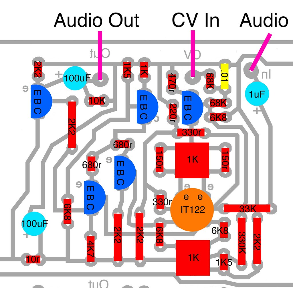
This is the Buchla System 100 Gate (110 VCA) circuit, directly from the schematic, part-for-part, four of them on a single home-etch PCB. Of course you only have to stuff a pair if you wish a "true" 110 clone, but:
"YCNHEVs."
IMPERATIVE: The power capacitor (100uF on the lower right, between +15V and ground, is reversed and will fry. The "+" has to be connected to +15V. Reverse the polarity from what is indicated on the PCB/artwork!
Power:
Friendly, requiring only ground and +15VDC.
Audio signal levels:
The 100 system is a tad quieter than the 200, being around 1.2VRMS, a bit below "line level" consumer gear levels (CD player outputs, etc.). 200 system audio might be a bit hot for this device so use the provided input attenuators as required.
This is not for direct use with Euro and "modern" 10V audio level modulars, although you can certainly run them in through the attenuators to avoid distortion, but the output levels would then require boosting. It should however be directly compatible for use with Moog, Technosaurus, and other systems making use of this legacy signal strength specification.
If you fully open the gate with +15V with no input audio signal present, you will hear a bit of hiss. A good SSM2164 VCA circuit will exhibit a lower self-noise floor. As with the Moog Modular 902 VCA, you may hear some of this self-noise when gating very dark, low-passed signals or sine waves. Brighter signals should completely mask it.
Control requirements:
This is a 100 series module and it requires a +15V CV signal to fully open. Such signals are available from 100 series envelopes, the 410 Module Cluster envelopes, and the 280 and 212 Dodecamodule envelopes (perhaps also the 284; I do not know).
To use properly with later 200 and 200e modules, see the Modifications section at the end of this post.
Parts:
Although the original utilized the matched dual IT122 transistor, other 110 builds indicate that a pair of unmatched 2N3904 transistors may instead be used in its place and made up for via the provided trimmers. The 2N3565 may also likely be substituted for with 2N3904 or perhaps BC550B or C.
Linear Systems make an IT122 equivalent, the LS122, available through your LS distributor.
Nothing else is particularly special, but make sure that C2, the positive rail smoothing cap, is at least 35V or higher. C1 and C3, in the signal path, can be 15V or higher.
I've never seen a 110 in person so I don't know if Don used a tantalum cap for the 1uF.
The original likely used a majority of carbon composition type resistors. Carbon film 5% are fine. Metal film 1% are boring.
The trimpots have a very tight footprint. I use these but the front leg must be bent out and down:
8) Mouser
858-25PR1KLF
Note that multi-turn types will allow for more accurate nulling of the offset when doing calibration. I have not investigated which type would fit here.
Note that multi-turn types will allow for more accurate nulling of the offset when doing calibration. I have not investigated which type would fit here.
Capacitors:
4)
Elna II 1uF
Mouser RFS-50V010ME3#5
4) Elna II 100uF Mouser
555-RFS16V101MH3#5
4) 100uF 35V or higher
4) .01 film
Transistors:
4) IT122 or LS122 dual matched transistors or perhaps 2N3904
20) 2N3565 or 2N3904
Resistors:
1) 1/2W 2.2R resistor
20) 2K2
4) 10r
4) 1K
8) 1K5
8) 680r
4) 10K
4) 470r
4) 220r
8) 68K
16) 6K8
8) 330r
4) 33K
4) 330K
8) 150r 1%
Etch:
Single-sided to avoid suffering. No jumpers.

Bottom art reversed for etching. Click here to download a high-resolution PDF of the above from which to etch.
IMPERATIVE: The power capacitor (100uF on the lower right, between +15V and ground, is reversed and will fry. The "+" has to be connected to +15V. Reverse the polarity from what is indicated on the PCB/artwork!
Check for trace continuity:

Click here to download a high-resolution PDF of the above.
Wiring:

The original had a potentiometer per Gate, acting as an input attenuator. The input jack is wired to the right pot lug, the center lug to the "In" pad on the PCB, and the left pot lug to ground.
Of course, remember to keep clear which gate is being wired to which set of controls. Perhaps wire a Gate at a time and bundle the wires to prevent confusion and errors.

Ground wiring.

Audio wiring.

CV wiring.
Completed wiring, including ground wire to PCB:
Wire as indicated so the PCB and front panel "sandwich" closed. For any calibration or trouble-shooting, they will open to this position allowing plenty of space in which to work.
"CV" PCB pads are wired to the front panel banana jacks, deep blue color.
"IN" PCB pads are wired to the single front panel audio jack, green wire.
"OUT" PCB pads are wired to the pair of output front panel audio jacks, yellow wire.
To complete, solder a wire from the GROUND pad on the PCB to one of the ground lugs on any of the front panel jacks. Not shown here, must include for proper functionality.
Calibration:
I'm currently doing the following until a better method is made clear:
-With no signal connected to the Input, patch an envelope with minimum times to the CV input and repeatedly trigger it, adjusting one trimpot for minimal clicking, then the other, then the first one again as required. Full nullification of this is not possible with single-turn trimpots.
Front Panel:

Suggested front panel art. Click here to download a high-resolution PDF of this file, correctly sized. The characters "B", "C", and "D" are not exactly centered.
35mm or slightly less than 1.5" standoffs are used here with the parts side of the PCB facing the front panel. There is room for them when using Alpha or similar 9mm potentiometers. I'm not sure if 16mm pots will leave enough room for where the standoffs are indicated on the PCB.
In Use:
The Signal Level pots are to trim the input volume to avoid distortion. They do not open the VCA to continuously pass through the input signal.
Modifications:
1. It should be possible to wire a second pot to act as an offset to open the Gate to continuously pass signal. Wire the right lug to +15V, the center to the CV in banana jack lug, and the left pot lug to ground, per Gate.
2. (Theory based upon the 258 and 291...UNTESTED HERE) Replace R8, 68K, at the CV Input pad, with a 47K or so to use with 200e and later 200 system modules and clones which output 10V CV signals.
Disclaimer: Nothing here is approved for commercial application.