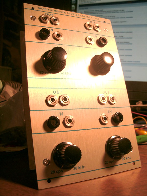
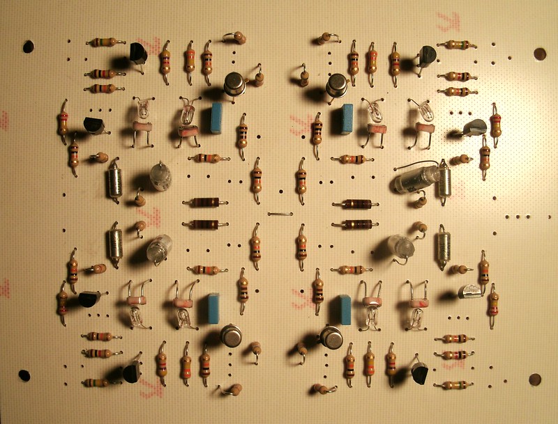
This is the filter from the Buchla 410 Module Cluster found only in the CBS Performance III instrument. It is a slightly later version of the 192 dual opto LPF module, which some modified for CV in alongside the front panel Frequency pot. You might have to have an account on flickr.com to see Buchlajoe's photo of a 192. Note the shrinkwrap for opto isolation; not sure if the distance provided alters the response characteristics.
Edit: It IS basically the same circuit as the Buchla 192 opto LPF which originally lacked CV inputs (the pot provided 0-15V). I've modded this 410 circuit into a 192 and they sound and act alike. The 192 loses the negative voltage rail. Thanks to the user who shared photos of a vintage module!
It uses +/-15V power rails and incandescent lamps and photoresistors. I dropped in 14V lamps and the only type of photoresistor at my local surplus dealer and it works perfectly.
As lamps are slower than the LEDs in vactrols, expect a much slower decay, especially if you're only used to the 5C3 vactrol!
On my build I find the filter closes completely at minimum CV input, cutting off bass lines and bass drums as I fed CDs into it. It doesn't quite open all the way to pass through the very highest frequencies; this may be due to the lamp and photoresistor combination I've used. Your experience may vary.
Quick soundbites:
https://soundcloud.com/peake-1/410-lpf-158a-saws
https://soundcloud.com/peake-1/410-lpf

Test build.
SCHEMATIC:
http://rubidium.dyndns.org/~magnus/synths/companies/buchla/Buchla_4100_8_200.jpg
COMPONENTS:
The 2N4339 is again available at mouser although they're a bit pricey. For this use, a J201 might suffice. There is a Vishay 2N4339-E3 but I haven't tried it out. It's less expensive than the InterFET version. J201 at mouser are $3.30, part #106-J201.
The original used the enormous Mallory PVC large film type capacitors found throughout the 100 series and in some 200 modules. It's thought that like the 910pF ceramic capacitors found in certain non-critical spots that Don had access to military and consumer surplus deals and used them applicably. The good news is that the Mallory PVC have become known as good-sounding. Modern "Orange Drop" capacitors are fully applicable for this circuit as well, although large pitch solder footprints have not been provided for them. Vishay MKP1837 and 1830 "ERO" film type box capacitors with a 5mm pitch are fully acceptable and they have a very good reputation for sonics in certain circles.
The 2N3565 may be swapped for 2N3904 or other generic NPN. The 4248 may be swapped for 2N3906 or other generic PNP.
The only electrolytic capacitor's value is a bit difficult to suss from the schematic; it looks like 100uF. 10uF might be fine in the same place; I don't know. I've used a 100uF audio grade Elna Silmic II in my recent perf build and it's fine.
Provision is given to include on the trace/solder side, a pair of "D" case 15uF tantalum capacitors for power smoothing.
ETCH AND PARTS LAYOUT:
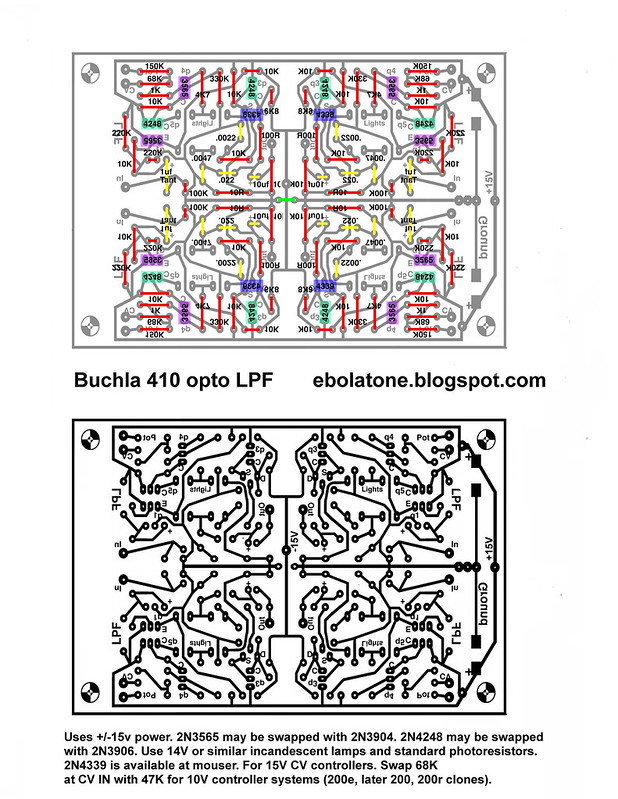
Click here to download the PDF from which to etch.
PARTS LAYOUT:
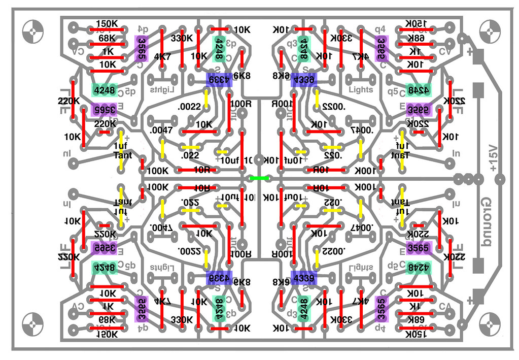
Note the single short bare wire jumper at the center of the PCB, as well as that being where the -15V supply is fed. You may optionally solder in "D" case 15uF tantalum SMD capacitors of the type used in Roman's builds for power supply smoothing.
Yes, I've taken my artwork from the 410 build and copied and flipped it around to create this layout, causing the text and parts legend to become reversed in places. I'm leaving it like this in the interest of saving the time it would take to do a cosmetic and applying it to module builds and the development of new module layouts. I'm pleased with the symmetry apparent in this layout.
CONTINUITY:

RESISTORS:
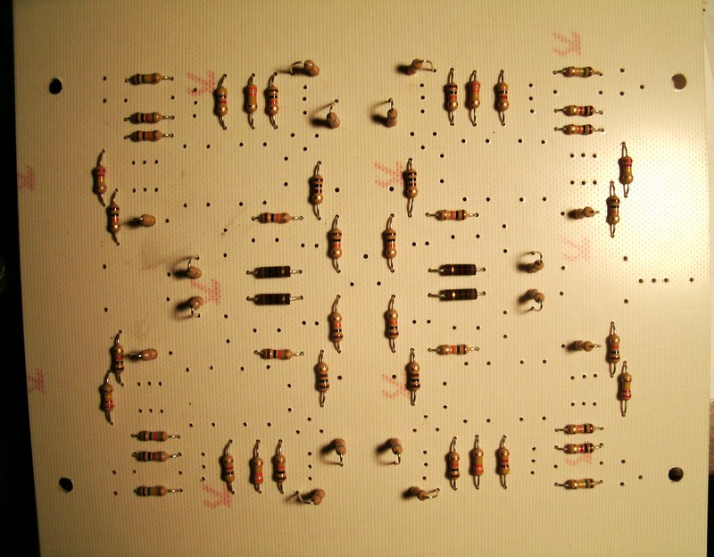
Before worrying about isolating the lamps and photoresistors you'll want to do the standard pre-power check-over...looking for any solder bridges, cold solder joints, etc.
POWER IT UP:
With no other connections besides power, the lamps should all be fully dark. A single reversed PNP transistor can cause most of them to slightly illuminate as well as not function properly. You of course need to confirm full functionality prior to sealing up the opto sections.
Using an alligator clip or probe which is connected to +15V, touch it to the input side of each 150K resistor (toward the input solder pad). Both lamps per quadrant should fully illuminate.
ISOLATING THE OPTO SECTIONS:
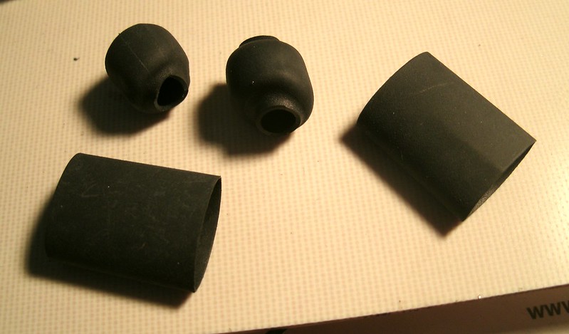
You can take a 1/2" diameter piece of black shrink wrap to isolate the lamps and resistors, one tube per lamp + resistor and seal the open ends with epoxy or electrical tape.
The lamps and photoresistors may need to be directly in contact with each other. Checking this out...
FRONT PANEL WIRING:
I'm going to use interrupting audio jacks on the two right-side filters so that the audio output of the left filter normally runs into the second; this will result in a 24dB cutoff slope at the output of the second filter. Modulate both filters equally with the same source(s). To use the second filter independently simply plug in an audio jack.
The CV pots have +15V to the right side lug and ground on the left, with the center lug going to the Pot in solder pad at the 150K resistors at the outside corners of the PCB. The CV ins can be wired directly to the input banana jacks or you can put a 10K pot in this path, in to the right lug, left to ground, and center to the PCB CV input solder pad.
Note that I've supplied extra ground and +15V solder pads which are to be wired to the front panel as needed. Don't forget to wire a ground wire to one of the audio jack ground lugs. One is fine; you don't have to chain all of the audio jack grounds. The front panel acts as a ground plane to all audio jack grounds. This is how Don did it.
MODS:
This module is from the Buchla era of 15V CV controller ranges. To use with 10V types (later 200 modules, 200r clones, and 200e systems) swap the 68K resistors at the CV IN solder pads for 47K or similar value resistors. Exact values have not been determined in use.
Adding resonance: Working upon a daughter board with opamps to provide resonance. Will be optional for purists wishing to avoid any and all opamps in their 100 clones.
Note that the 106 mixer cannot be used to add resonance to this circuit; the 106 sums both sections to the "ALL" output, and you need a single inverting section to be independent of that output. You can of course disconnect one of the sections from the ALL output by removing its 68K resistor to the ALL summing section, but there is not enough gain in the circuit to produce more than a very subtle increase in resonance.
RESONANCE:
The circuit appears to behave as do ladder filters when resonance is increased: the passband reduces in volume. This means not so much bass when you increase resonance...but with four filters, you can run two in parallel and sum them in a mixer, one with res and one without...