Those who have known me long-term remember that I've praised the Moog Modular to the high heavens as being an amazing-sounding instrument, superior to modern designs. Among the aspects which have since been proven out, the CP3 discrete mixer saturates/distorts very pleasantly when slightly overdriven. Random oscillator fluctuations presenting a saturated bliss...even before going into that amazing filter. I was given a great deal of shit for being right.
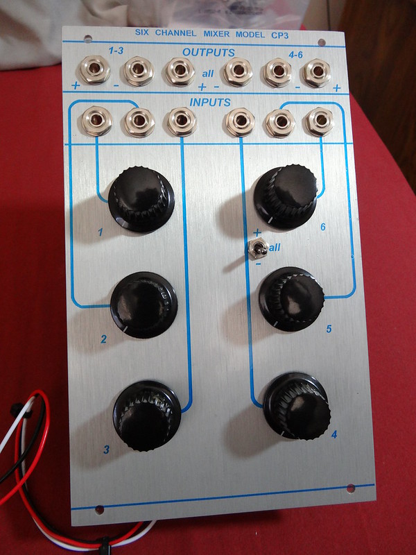
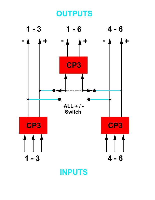
SO. Why not add such goodness to the Buchla? Especially interesting for those using the 200e, 259, and 208 devices which would benefit from some pleasant saturation. Here we have three CP3 mixers, acting in place of the 106 discrete mixer. It behaves in the same manner, two independent three-channel mixers with their own outputs, also feeding into a final summing mixer for a single output combining ALL of the six input signals. But here, the CP3s positive and negative outputs are provided as they apparently sound different so it's up to the user to determine which for them is the most attractive in whatever patch. The "-" output is said by some to be the most attractive-sounding. Note that the individual 106 sections were inverting, so use the "-" output to mimic 106 patching such as in adding resonance to a 292 channel via feedback.
Switching is provided to determine whether the mix section A and B positive or negative outputs are sent to the summing ALL mixer section.
Here is a scientific exploration and explanation of what the circuit does to embiggen input signals with a very interesting short video.
PARTS:
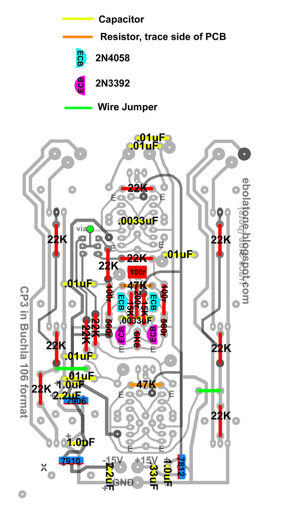
The original used plenty of carbon composition resistors and every now and then 1/2W carbon film. It is possibly useful to have the 15K and 560r matched or 1% metal film. It is unknown if the carbon composition resistors used in the original circuit were matched to any extent, but since they were likely 10% tolerance types. Modern carbon composition resistors are available in 5% tolerance so you're already that much closer to any required matching.
Transistors: The 2N4058 and 2N3392 are again being manufactured and are available through Mouser.com. They retain the pinout of the vintage transistors, ECB.
You can use matched 2N3904/2N3906 but I'm not sure if it will sound the same; also, remember to make them fit the provided ECB pinout on the PCB! 3904/6 are usually EBC. One build page did indeed say the 3904/6 sound a bit edgier than the original transistors.
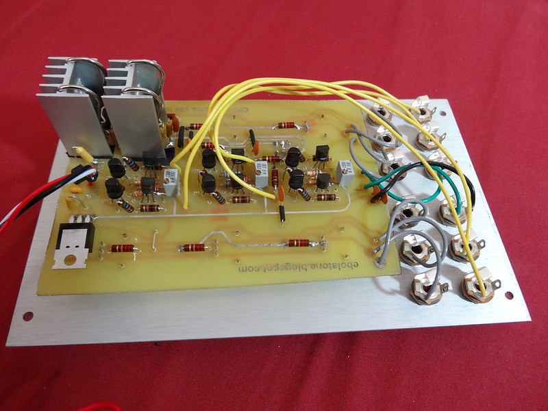
The heatsinks were overkill to insure functionality on that revision; you can probably get away with using two of these with nylon 4-40 type screws/nuts on the negative regulator ICs. Be sure to use a little electrical tape to protect the sinks from shorting upon any PCB traces.
The ones used in the build in the picture are here. They require electrical tape between them and the PCB to avoid any shorting. You also have to sort of slide in the power IC as you bring the clip down upon the body in order to secure the power IC. They are also through-hole designs so there are a pair of 1.5mm holes required in the PCB; drill holes are already provided. The feet must go through the electrical tape.
Also, some of the capacitors seated directly at the power ICs require solder on the top and bottom side of the PCB so first install the 7910 and then the caps and then the 7906 and caps. The potentiometer beneath this pair requires the leg which goes through the PCB to be clipped off lest it touch the heat sink.
512-LM7812CT
512-LM7910CT
863-MC7906CTG
2) 2.2uF 74-173D225X9025VWE3
3) 1.0uF 74-173D105X9025UWE3
3) .0033uF 23PS233
6) .01uF
2) 47K
3) 6K8
3) 200r
6) 100r
6) 560r
6) 15K (might want 1%)
11) 22K
3) 100r trimpots 858-64WR100LF
1) Toggle Switch 611-T201-001
6) Davies knobs 5164-1610AA
12) Tinijax 502-41
12) Tinijax nuts (one each, behind the faceplate)
1) EDAC 587-306-50-010
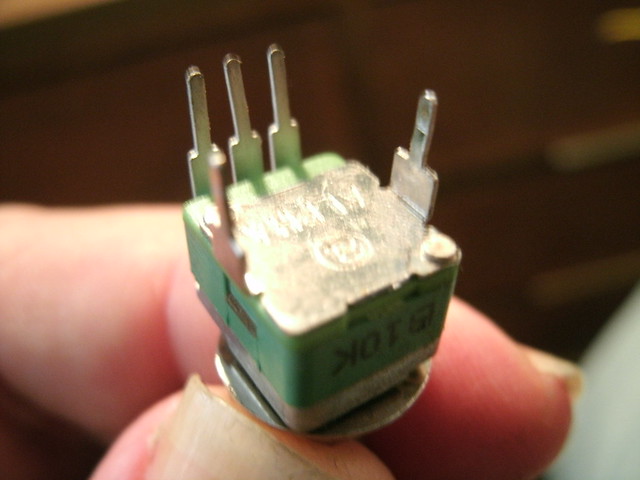
6) Alpha 9mm Audio A25K right-angle pots
MATCHING:
Gain needs to be matched between all transistor pairs to say within 5%. I'm not sure if all transistors of the same type need to be within a common 5% or not for equal audio levels.
GAIN STRUCTURE:
The original mixer is a 2X gain increase with an overall level control. The earliest Moog oscillators, the 901b and 901, were 1.2V output. The Buchla 100 oscillators I've cloned are supposed to be quieter than the 258s, but they aren't for some reason. The gain structure of this mixer and the differences in level mean saturation will occur at different points of the input Level controls so keep that in mind per the system in which you intend to use it. You may have to change the 22K input resistors to a different value if you're getting saturation before the 12:00 setting.
Signal sources greater than Moog and Buchla will require input resistor value changes.
Use 47K resistors for the two input section CP3s for 2X gain. Use a 22K on the top CP3, which is the summing section for both input sides, for unity gain so as to not overdrive everything too far when using 4+ inputs.
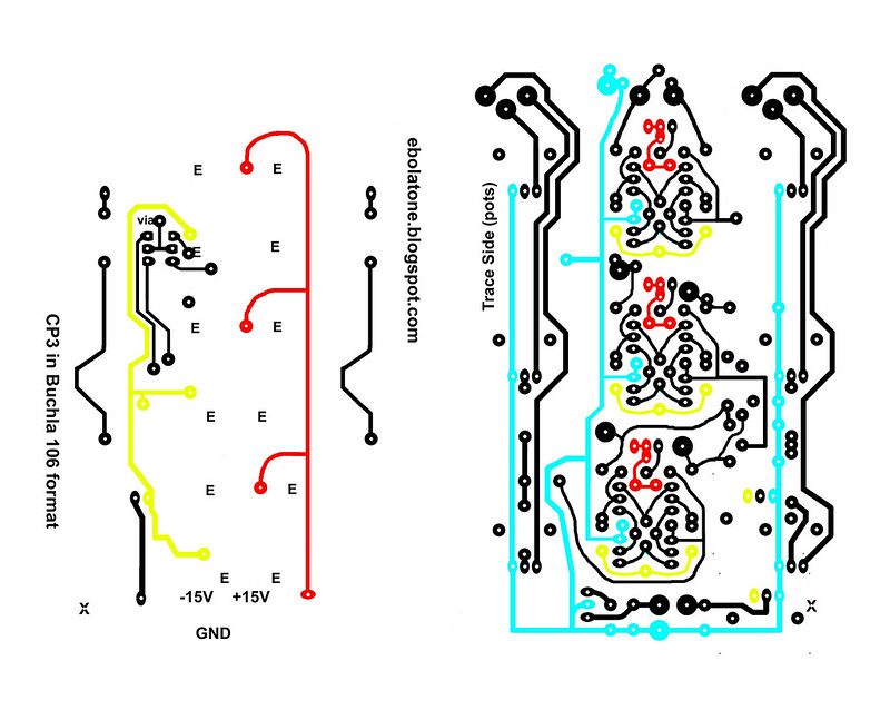
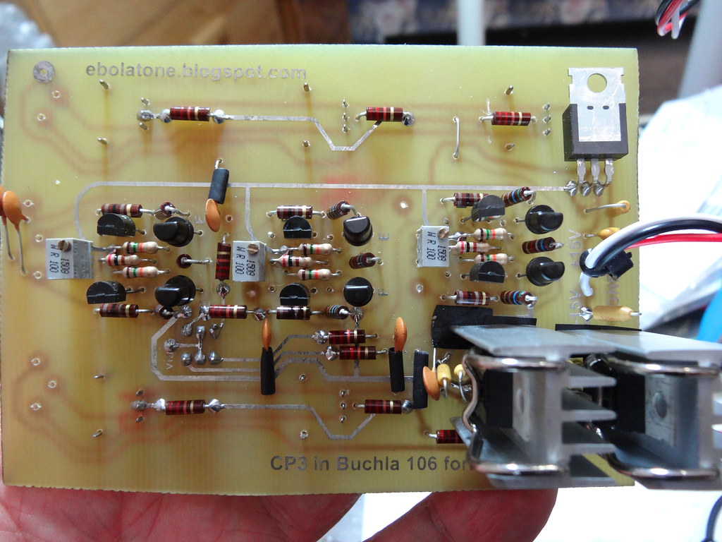
SOME PARTS ARE MOUNTED ON THE MAIN TRACE SIDE:
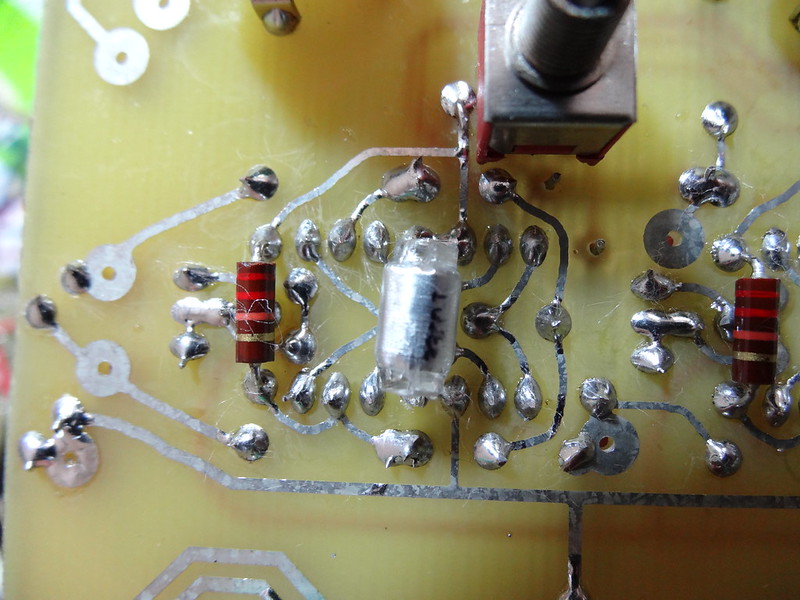
Some resistors, caps, and the potentiometers are mounted on the side with the most trace artwork. The .0033uF caps, definitely. Some of the .01uF caps can if you pay attention to using heat shrink to avoid shorts with PCB traces. The feedback resistors for each CP3 are on the trace side, as are the pots and the switch.
ETCH ARTWORK
may be downloaded HERE.
ALIGNING THE TWO SIDES FOR EXPOSURE:
Two drill holes have been provided for alignment; the solo hole at the outer edge of where the power ICs are stuffed, and the large input pad across the PCB from there which is on both sides.
Remove the protect from one side of your two-sided PCB. Tape the trace/pot side art down. Carefully drill through these holes using a #64 or so drillbit. Fold back the transparency and brush out any particles from drilling. Expose that side. Remove the protect from the other side and align those holes over the drilled spots. Tape it down and expose.
PARTS AND CONTINUITY
Some of the jumpers must be covered with heat shrink or similar in order to prevent shorting traces on the PCB.
Don't forget the VIA! Using a resistor leg clipping or similar, insert it through the pad and solder one side; bend it down and solder the other, then smooth down the first solder point.
You'll have to make some modifications to each potentiometer as follows:
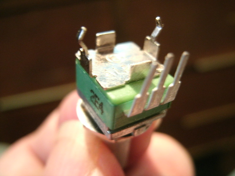
Stock Alpha 9mm PCB-mount snap-in potentiometer, unmodified.
The two spacing tabs need to be removed. This is as simple as grasping each with a plier and rocking it back and forth until it breaks off.
The two mounting legs need to be straightened; simply pinch them with a plier:
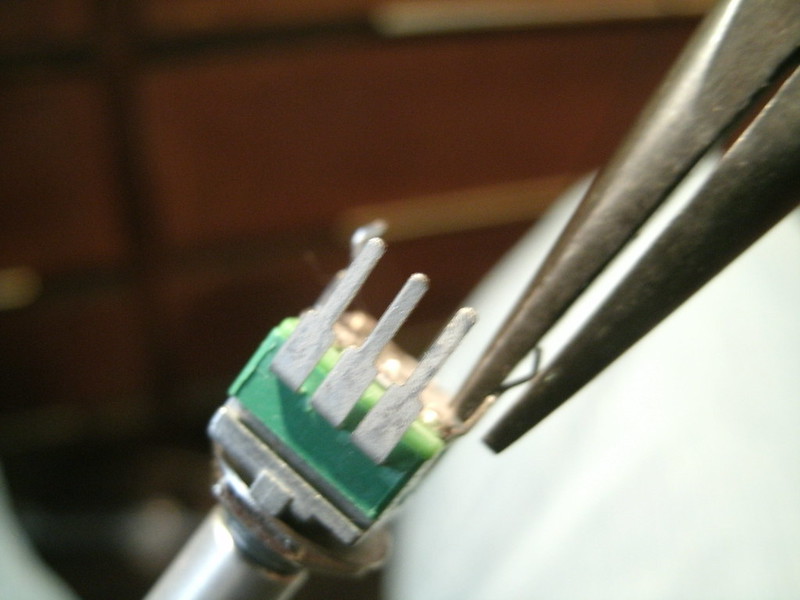
And a metal nub at the front must be removed; a dyke hand tool or a large pliers can take care of this:
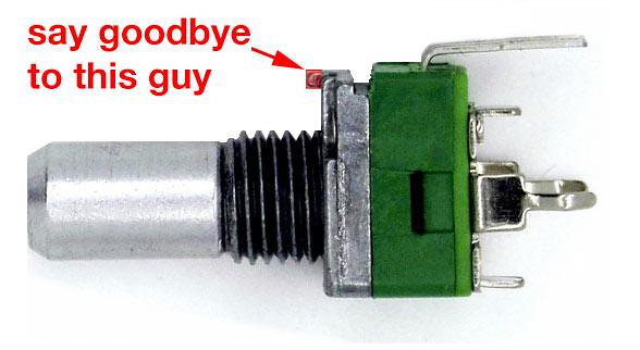
Image via THONK, who sell these with the nub already removed. Thanks!
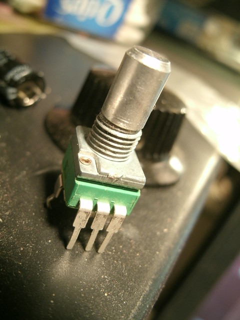
Finished! This is what they'll need to be for this build.
THONK will be stocking these with the nub already removed:
http://www.muffwiggler.com/forum/viewtopic.php?t=122962
If you're using the large heatsinks you'll need to cut the side pin on the pot which will mount beneath them so it will not contact the sinks.
PUT A BRIGHT LIGHT BEHIND THE PCB AND CHECK THE POTS FOR ANY SOLDER BRIDGES:
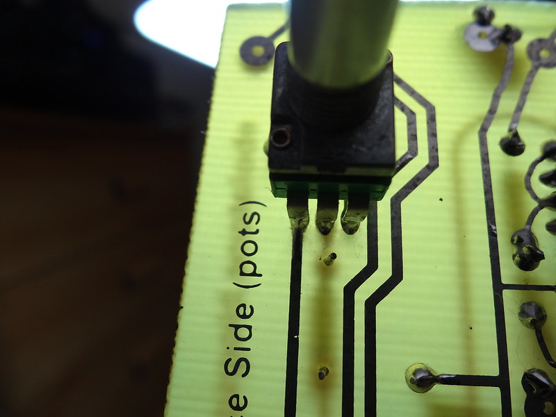
This is how all of them should look.
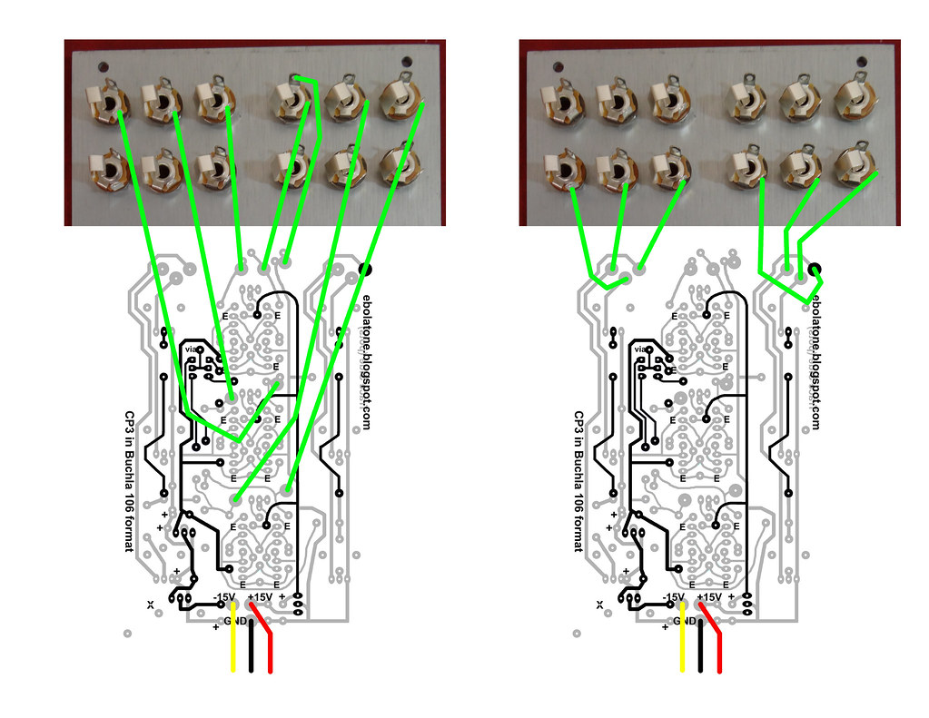
WIRING:
CALIBRATION:
Put a VOM reading DC to the outputs and set the trimpot for each section for a minimum DC level. If it's greater than 0.5V in either polarity you might need to use 1% 15K resistors.
SUGGESTED FRONT PANEL ARTWORK:
Download HERE.
MATING THE FRONT PANEL AND PCB:
I like to use three Alpha washers on each pot to hold them slightly back from the front panel; I've found this is the perfect spacing to allow the small Davies knobs to sit all the way upon the shaft but still slightly off of the front panel, allowing you to sit them and tighten them down without worrying about them scraping the front panel when turned, as well as providing a unified appearance. The switch requires some washers as well and the nut will sit flush with the top of the switch's shaft. Looks great!
The pots will align with the holes but the switch paddle must be moved by hand to center through its hole.
TROUBLE-SHOOTING:
-If the ALL outputs are silent, did you remember to install the VIA wire?
-If one or more CP3 circuits cannot be trimmed down to a 0.2 or less offset voltage, swap out the 15K resistors for 1% types.
Super extra thanks to guest at Muff Wiggler and Scott Stites without whom this wouldn't have happened!