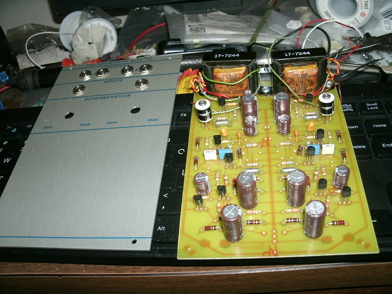
The 190 dual reverberator is called "the" Buchla 100 sound. It's entirely discrete using only transistors and transformers with a single Amount pot crossfading between in input signal and reverb return. Note that it uses a +24V supply but that's provided in the 100 power supply. If you don't have one of those, small +24V supplies are pretty inexpensive in the form of a wallwart from Mouser, etc.
I have been told that this is a single-ended Class "A" 1W amplifier (into the reverb tanks). That may partially explain why the 190 is so very good-sounding...
SCHEMATIC
Buchla 190 Schematic
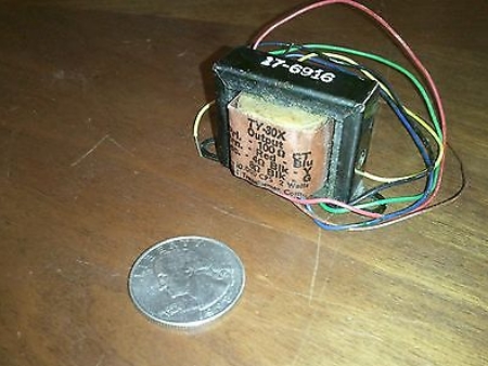
Sowter 1427a transformer wiring:
Yellow- +24V
White- Collector pin of 2N3053
Green- Ground of reverb send to tank
Brown- Audio of reverb send to tank
Red and grey are unused.
Matching to the Triad TY30X transformer colors listed in the schematic:
Triad: Sowter:
Brown Yellow to +24V
Blue White to Collector pin of 2N3053
Black Green Ground of send wire to reverb
Green Brown Audio of send wire to reverb
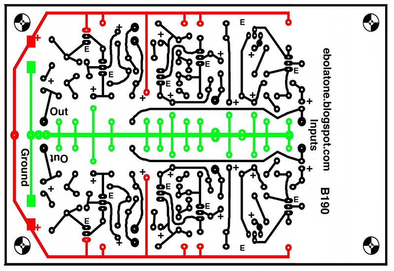
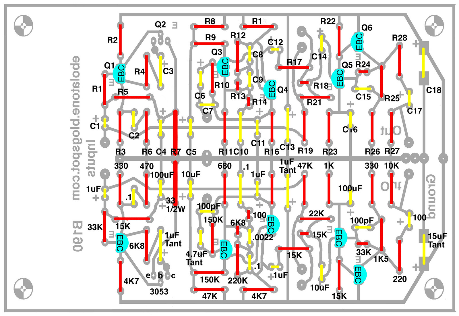
ETCH ARTWORK AND PARTS LAYOUT
Download HERE
COST:
2) Accutronics tanks: average $30.00 each; "MOD" versions are less but sound different.
2) Sowter transformers: $110/pair, which is significantly less than vendors charge for the original TY30X/Magnetek.
2) Quality heat sinks: about $30.00. You can use less-expensive sinks but this should extend the life of the 2N3053s.
This build will likely cost over $200.
CABINET COMPATIBILITY:
The transformers are 30mm tall by themselves, so figuring with 15mm standoffs for the PCB plus PCB and transformers, 50mm or so deep behind the front panel.
Clone using original Triad transformers:
The main issue with doing a 190 build used to be the Triad TY-30X 2W audio transformers. These were also used in the 410 module as well as the 212 Dodecamodule (for the headphone output).
Here it is in a 1961 Triad catalogue:
http://www.triadtransformers.com/images/bigArchive/TR-61%20pg-010.jpg
And in 1978:
http://www.triadtransformers.com/images/bigArchive/TR-77~78%20pg-030.jpg
"Output and driver transistor transformers: High level
Primary matching impedance: 100CT
Primary current: 100ma DC Balance
Maximum level: 2W
DC resistance Ohms DC: Secondary: 8/4 Ohms; Primary: 14.4 Secondary: 1.1 Overall Turn Ratio: 3.54:1
Freq Response +/-3dB: 50-10,000"
MageneTek purchased Triad a while back and have an equivalent listed but I've yet to manage to source it in small quantities / initial order expense. They no longer manufacture transformers.
Triad tell me if they still have the technical papers, it would cost $2500.00 to re-manufacture a run of them. I'd contacted both Hammond and Edcor looking for equivalents to no avail. Wiggler Mike Silver contacted Sowter and Brian quickly came up with a working clone!
Buy a pair of Sowter clones of the TY30X HERE. It is of course the 1427 Transistor output transformer. It is far less expensive than originals from vendors if you can even find them. I paid more than twice as much for a pair of originals and have seen them at far higher prices than even that! I've run a Kraftwerk track through the circuit with both transformers wired in and switched between them; they are really close, from this test on headphones. I haven't checked to see if they begin to distort at the same level.
The 100 series apparently used the now-rare Mallory "white" axial electrolytics (100uf 15V; 10uF 35V), which =might= play a tiny part in the overall sound.
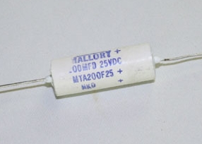
For illustrative purposes, a 200uF Mallory of the type used in the vintage module. Image from tedss.com, who do not appear to have these in 100uF 15V or 10uF 35V.
No space is provided here for them if you can source them; instead, common types may be used although it in the interest of "fidelity" it is recommended to use Elna Silmic II "audio" type capacitors, being the budget choice for higher performance over common caps. Most of these caps used in this build should be radial, not axial types.
The 190 also used several huge Mallory film capacitors, .1 and .0022 values. This also may play a part in its character, as well as that there are several tantalum caps involved in the audio path (1uF, 4.7uF).
There are two types of Tantalum capacitors in the original module. The 1.0uF are mainly Sprague
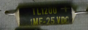
1uF (C
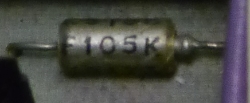
1uF (C
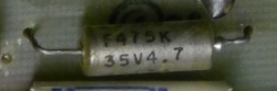
4.7uF Tantalum
The same is true of the three film capacitors, 0.1uF and 0.0022, which are C8, C9, and C10. Originally they were the very large Mallory polyester types, a very deep red coloration. The 0.1uF were 100V and the 0.0022uF I believe was 400V or so. You can certainly use Orange Drop equivalents (specifically polyester types) but you'll have to crimp the leads as adequately pitched (spaced) solder pads are not provided.
Several of the resistors are carbon composition types: 470R, 4K7, 47K, the 33R 1/2Ws, 1K, 10K, and 220R. I do not know if this was due to any particular strategy or finding on Don's part. His 258B schematic indicates specifically that certain values were to be carbon composition types; again, it is unknown "why". There are only a couple CC types in some of the later 258Cs I've seen.
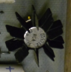
TO5/TO39 can 2N3053 mounted on the 190 PCB.
Edit: I am told that this is a 2N3053, which is also NPN, and is easily available in the above form, which is TO-39, from Mouser. The hand-written schematics are for the most part not a problem from which to extract parts numbers and values; in this case, the kicker is that there probably were never TO5 2N3055, which should have alerted me immediately. You can just barely tell that the schematic says 3053 and not 3055. Very sharp eyes...Thank you!
2N3053 from Mouser (Temporarily out-of-stock and it's the only one available from Mouser.)
The 3053 run exceptionally hot so use a good heatsink such as this: 532-1130B or 774-TXBF032025B.
TEST THE ETCHED PCB FOR CONTINUITY
After etching, confirm continuity with a VOM set to diode (hopefully one which beeps so you won't have to constantly refer to its display).
COMPONENTS:
BUILD:
The 33r 1/2W resistor mounts on the trace side if you are using the large Elna Silmic II audio capacitors. Nichicon FG or KZ types are perhaps even more desirable and they're smaller.
It is important to attach the heatsinks to the 2N3053 prior to soldering them to the PCB. Also stand them about 5mm height above the PCB so they can breathe a bit.
REVERB TANKS
In the 100, the tanks were mounted inside the cabinet against the inside left and right sides. Terminal strips mounted inside the cabinet to the wood assist in the wiring task. I am told that the closest, if not exact modern equivalent are the Accutronics Type 4 with the following descriptor / part number:
4AB3C1B
http://www.accutronicsreverb.com/?PHPSESSID=b9752031617a105db2e4ad3e826ee4f0
They are easily available through eBay vendors and online guitar stores. Note that these are larger and are different than the tanks used in the 208r clone/group buy/etc.
Accutronics tanks are available and there is a newcomer called MOD who offer one quite similar, by the same name and spec, but it is typically less expensive. Here is a video I found of a comparison. The comments section indicates that the mounting of the new Accutronics might make a difference sonically...I find the MOD to be less blurry like you'd expect from classic reverb, and it's a touch metallic and meaty. The Accutronics to my ear has the blur you'd expect from a spring reverb or acoustic space.
WIRING
A wiring doc will be published shortly. Not much is a mystery but I'll provide visuals.
It is recommended to use existing long RCA male to RCA male stereo cords for each circuit's send and return to the reverb tanks. The tanks are color-coded with White input jacks and Red output jacks so maintain this continuity for ease of setup and tear-down.
The transformers can be mounted to the PCBs to save space if needed, but they're noisier that way, than if you mount them away from the amplification circuitry. If you do mount them on the PCB, I suggest using mu metal to seal them and to ground it as well.
A terminal strip can be mounted at the rear of the PCB. Tie the two +24V wires to one terminal input. The reverb send wiring may be done in the same way. Obviously, you'll want at minimum a 5 position terminal. In the original 15 module space wooden 100 Series cabinets, the audio transformers were mounted on the inside top, and used terminal strips to connect to both the PCB and reverb tanks, each of which were mounted inside of the left and right cabinet sides/panels.
POWER
The 190 uses Ground, +15VDC, and +24VDC.
Get an inexpensive 24V supply here. 1A might be too much but I believe in headroom.
SUGGESTED FRONT PANEL ARTWORK
REFERENCES / FURTHER READING:
Check out Mark Verbos' installment on the 275 dual reverb for a pic of the later mounting style: naked springs suspended in an aluminium boat atop each other along with the driver electronics.
http://buchlatech.blogspot.com/2012/11/spring-chickens.html
Errors in the CBS Buchla Schematics?
Carbon Composition Resistors in Buchla Gear
Huge thanks to JonDent, Benge and Jason Butcher for information and guidance! And "blame" Opsysbug on Muffwiggler.com for believing I could do this, which is why it now exists. ;) Thanks to Mike Silver for finding the right company to clone the transformers!